Year 1, Semester 1
CAD WORK
 Paper Fold House
<
Paper Fold House
Paper fold house
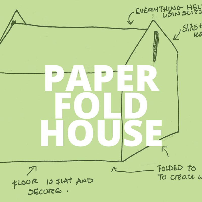
The Paper Fold House was our first project, so I understandably found it quite difficult.
We were tasked with creating a house design on CAD that could be built only by folding paper or card. No glue or tape was allowed. Attachments must be created using tabs or something of the like. It also had to be created using only the new skills we had learnt on AutoCAD
I began by sketching out my idea, taking inspiration from the pets at home disposable pet carriers. It was difficult to try and determine in my mind whether the lengths and heights would work together to make the sides fold, which is why I drew a small 3D sketch to make this thought process easier.
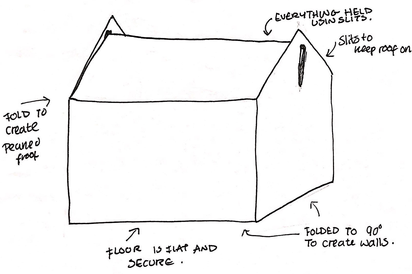
To begin the process of drawing the design in CAD, I started by drawing the middle rectangle using the line tool to create single lines rather than a poly-line. I then used the reflect tool to reflect my lines so that they were symmetrical with the original lines. I did this until I had 4 rectangles around the original one. This part was rather easy, but it did help me to practice the use of other tools that I don’t usually use. I then added the smaller rectangles and the triangles using the poly-line tool. The last part I did is was probably the hardest, as I didn’t know how to change the folding lines from solid to dotted.
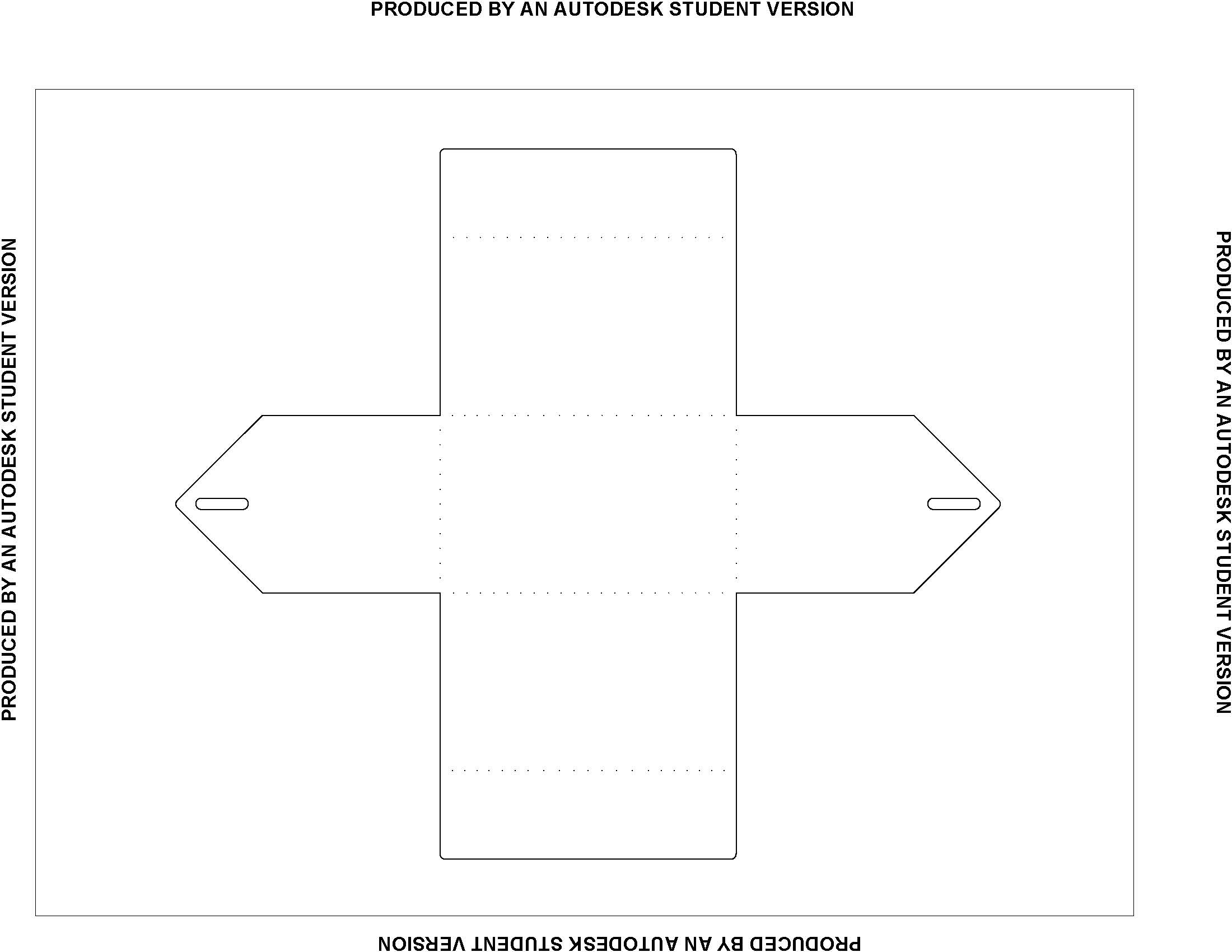
All in all, I am happy with the outcome of my folding house. For a first project, it is basic, but I would say decently designed. Although I am not sure if it would work if printed and folded.
The only thing I would have done to improve would have been to print it out and try folding the house into position to evaluate whether it works as a 3D object.
The Paper Fold House was our first project, so I understandably found it quite difficult.
We were tasked with creating a house design on CAD that could be built only by folding paper or card. No glue or tape was allowed. Attachments must be created using tabs or something of the like. It also had to be created using only the new skills we had learnt on AutoCAD
I began by sketching out my idea, taking inspiration from the pets at home disposable pet carriers. It was difficult to try and determine in my mind whether the lengths and heights would work together to make the sides fold, which is why I drew a small 3D sketch to make this thought process easier.
To begin the process of drawing the design in CAD, I started by drawing the middle rectangle using the line tool to create single lines rather than a poly-line. I then used the reflect tool to reflect my lines so that they were symmetrical with the original lines. I did this until I had 4 rectangles around the original one. This part was rather easy, but it did help me to practice the use of other tools that I don’t usually use. I then added the smaller rectangles and the triangles using the poly-line tool. The last part I did is was probably the hardest, as I didn’t know how to change the folding lines from solid to dotted.
All in all, I am happy with the outcome of my folding house. For a first project, it is basic, but I would say decently designed. Although I am not sure if it would work if printed and folded.
The only thing I would have done to improve would have been to print it out and try folding the house into position to evaluate whether it works as a 3D object.
 Artistic Design Poster
<
Artistic Design Poster
Artistic Design Poster
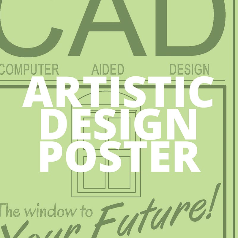
For the artistic design task, we were asked to create a poster. It could be of any topic of our choice. We had to use the skills that we had learnt so far to make the poster look as pleasing as possible.
I decided to make my poster very simple and relating to CAD. I used the rectangle tool, poly-lines, text and hatching to create the poster. It has a very simple window drawing in the centre, with text going across at an angle above. I decided to use light blue and black as the main colours so that I didn’t over complicate it.
One issue that I repeatedly had was the lines wanting to lock onto other lines automatically. This caused an issue as when I was trying to create the window, for example, the auto lock would make all the rectangles start at the same point (the corner of the original shape) rather than in the middle. Luckily it was an easy fix, I sorted this issue out by turning off the auto lock feature and everything was back to normal.
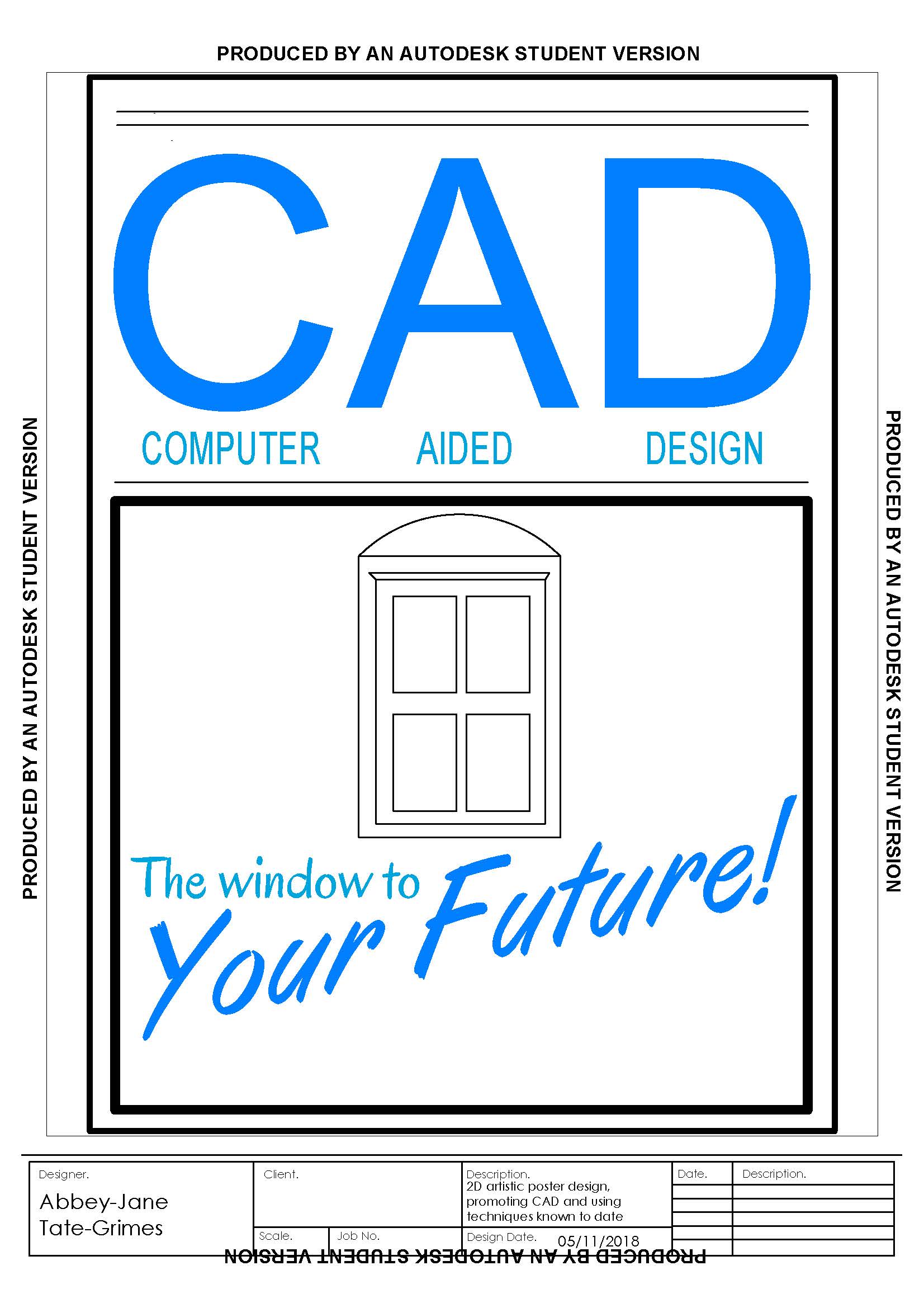
I believe it does look good and is pleasing to the eye but could be improved. The poster uses a mix of fonts, coloured hatching and line work which all work well together. When I made the poster my CAD skills where only just being learnt so it is not as design based as I had hoped it could be; but as a first attempt at designing something that is meant to look good, I think I did the task justice.
For the artistic design task, we were asked to create a poster. It could be of any topic of our choice. We had to use the skills that we had learnt so far to make the poster look as pleasing as possible.
I decided to make my poster very simple and relating to CAD. I used the rectangle tool, poly-lines, text and hatching to create the poster. It has a very simple window drawing in the centre, with text going across at an angle above. I decided to use light blue and black as the main colours so that I didn’t over complicate it.
One issue that I repeatedly had was the lines wanting to lock onto other lines automatically. This caused an issue as when I was trying to create the window, for example, the auto lock would make all the rectangles start at the same point (the corner of the original shape) rather than in the middle. Luckily it was an easy fix, I sorted this issue out by turning off the auto lock feature and everything was back to normal.
I believe it does look good and is pleasing to the eye but could be improved. The poster uses a mix of fonts, coloured hatching and line work which all work well together. When I made the poster my CAD skills where only just being learnt so it is not as design based as I had hoped it could be; but as a first attempt at designing something that is meant to look good, I think I did the task justice.
 Layouts and scaled drawings
<
Layouts and scaled drawings
Layouts and scaled drawings (Title Blocks)
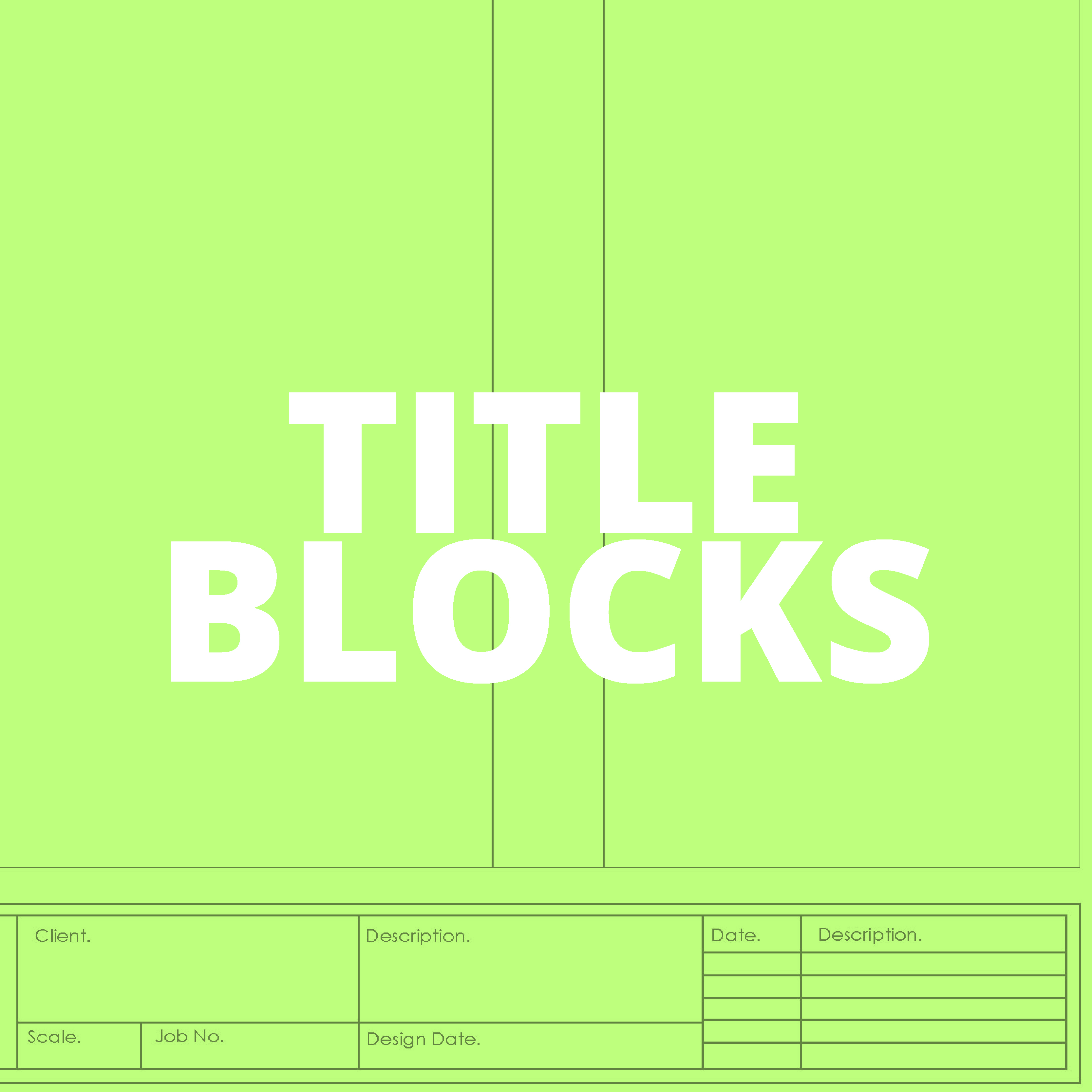
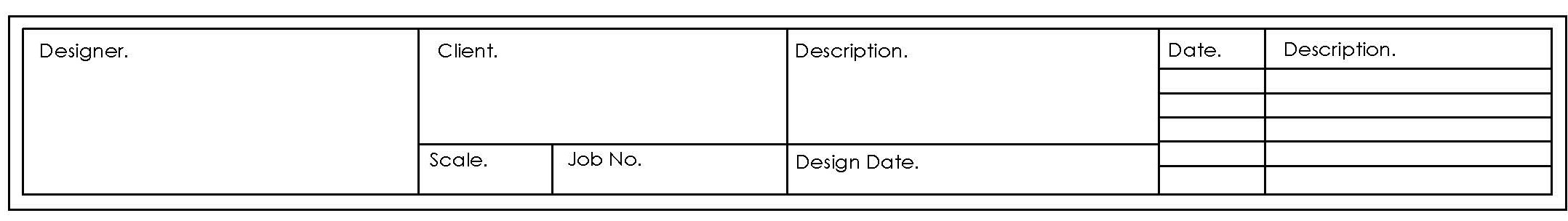
Title blocks are a tool that many designers use primarily in industry. They are a template that is laid onto design work after it has been completed. The template usually includes boxes for the designer’s name, the date, the client’s name and notes. The contents of the title blocks are purely up to the designer’s discretion and every designers title blocks look very different. Title blocks need to be easily adjustable for different work sizes and client requirements. They can be used for a tiny design in A4 all the way up to a huge design in A1.
For my title blocks I took inspiration from professional examples I found online. Each item needs a section with a title so that the client/examiner can look at the design and know exactly what it’s all about. Each section also needs to have enough space to be able to write in both on the computer and by hand once printed for adjustments. Finally, the sections need to be large enough to read the text within. If they’re too small it will be difficult to read the information.
I decided to make my title block one size fits all, which means that I could use the same one on any project, of any size or orientation. This is not just for ease but also to keep a theme through my work. It also means that every design has some left-over space to be able to write notes etc that need to be written on after print.
This the only problem I had with my one size fits all title block was changing it from A4 landscape to portrait. Thinking back, I should have started the design in portrait so that I know are fitted, but because I started in landscape I had to adjust the design to fit the portrait orientation.
All in all, I believe my title blocks include sections for each piece of the information I need and allow enough space for any information to be added. As they are one size fits all, it allows a theme to be Throughout all my work whether it be for clients or for class.
Below are images of all of the different templates of title blocks displayed in a PDF file. I have shown them in a PDF file as it means you can quite easily see the differences between each size.
 File Formats
<
File Formats
File Formats
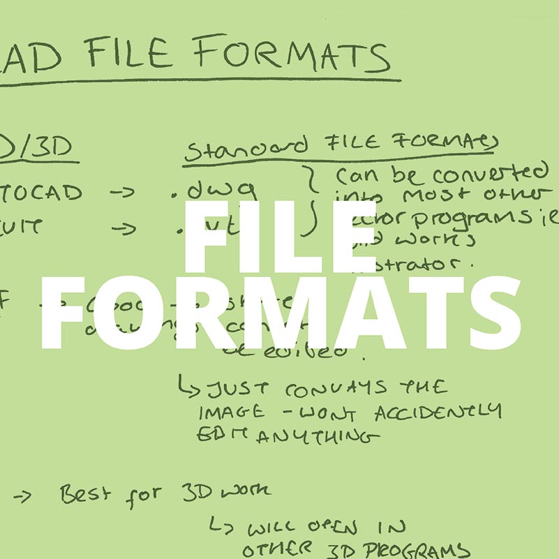
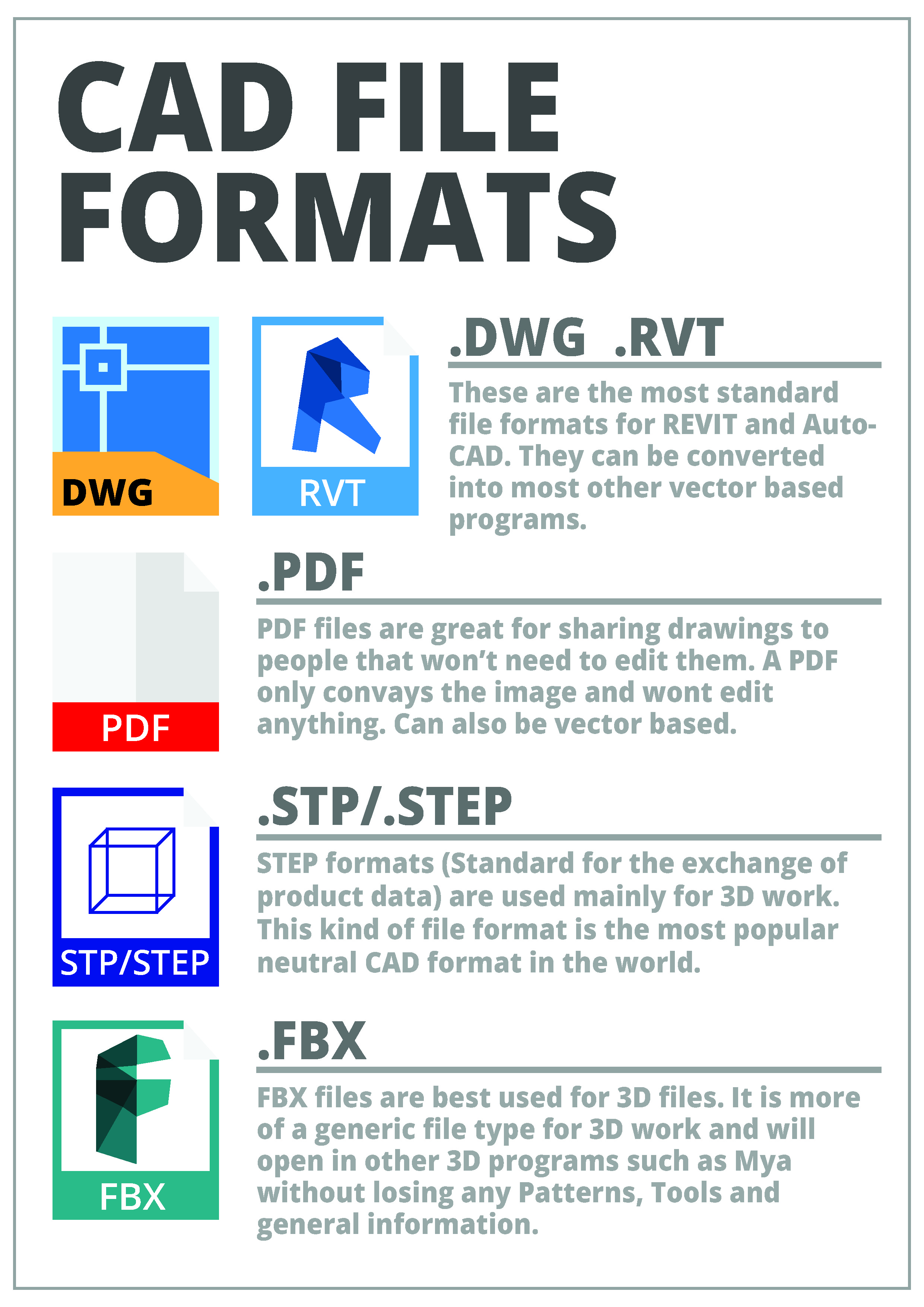
File formats are the different ways you can a save file. They range from PDF to JPG and everything in between. There are many different types of file formats depending on what program you’re using and what you are wanting to use the file for. The topic is particularly interesting, and in my experience, I easily forget which format is suited for what type of file. To combat this, I decided to make an info graphic briefly explaining which is which and to help myself remember the different types.
I decided to create a kind of infographic that outlined a small amount of information about each format. This way, it would be easier for myself to remember the key types, as well as anyone else I share the image with. Bright colours for the icons clearly separate each type and make it easier to remember.
I first decided to write out the information I wanted to use in a note from making it easier to remember. I also drew a brief design for the page and looked at the actual icons for the formats online and created a simplified version.
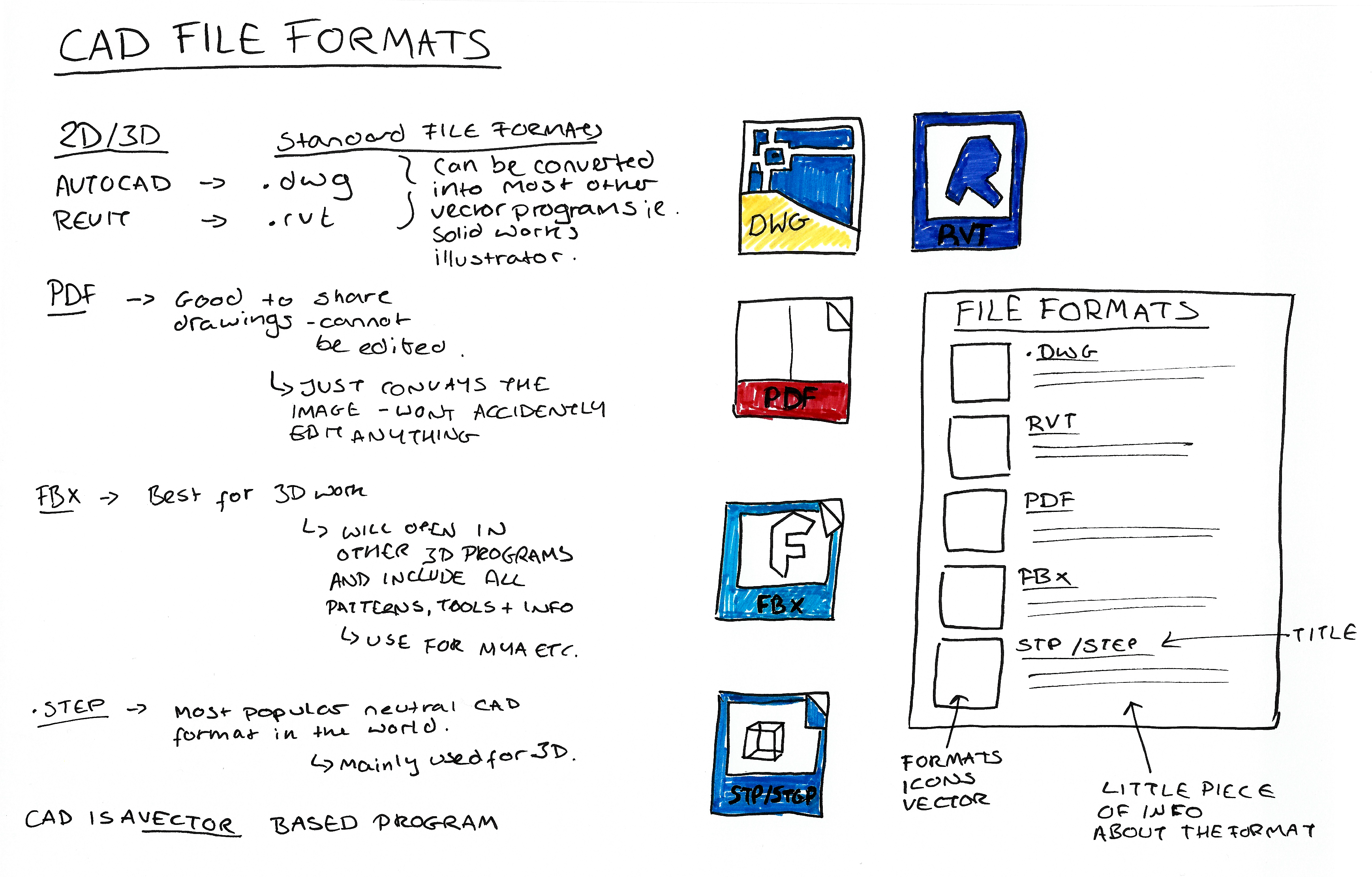
To create the infographic, I used illustrator. I recreated all the different format icons separately, using images of the actual icons to make them accurate. The font that I decided to use was 'Open Sans' with a mix between 'Extra bold' and 'Semi-Bold'. I decided on using grey shades instead of black as it is less harsh and easier to read.
File formats are the different ways you can a save file. They range from PDF to JPG and everything in between. There are many different types of file formats depending on what program you’re using and what you are wanting to use the file for. The topic is particularly interesting, and in my experience, I easily forget which format is suited for what type of file. To combat this, I decided to make an info graphic briefly explaining which is which and to help myself remember the different types.
I decided to create a kind of infographic that outlined a small amount of information about each format. This way, it would be easier for myself to remember the key types, as well as anyone else I share the image with. Bright colours for the icons clearly separate each type and make it easier to remember.
I first decided to write out the information I wanted to use in a note from making it easier to remember. I also drew a brief design for the page and looked at the actual icons for the formats online and created a simplified version.
To create the infographic, I used illustrator. I recreated all the different format icons separately, using images of the actual icons to make them accurate. The font that I decided to use was 'Open Sans' with a mix between 'Extra bold' and 'Semi-Bold'. I decided on using grey shades instead of black as it is less harsh and easier to read.
 Scamp Sketches
<
Skamp Sketches
Sketching (Scamps of Campus)
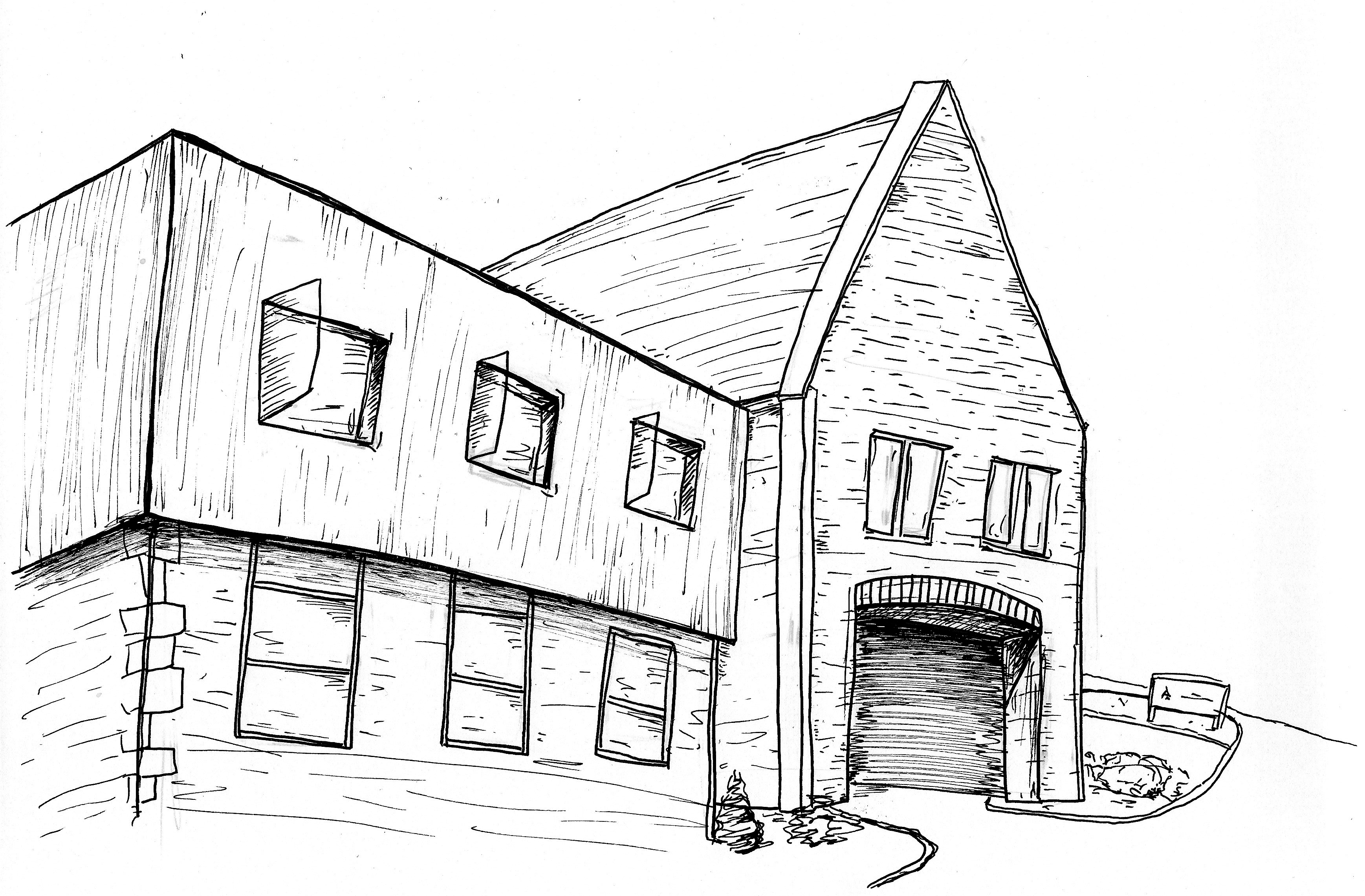
For our October break task, we were asked to draw scamps. Scamps are rough sketches that are relatively detailed but done quickly to grab a quick snapshot of an area. Our task required that we drew structures and areas from the University of Winchester campus. I drew two scamps of buildings on the Winchester campus.
I began by using a pencil to briefly outline the structures, then a 0.3mm fine liner to complete the drawings in a sketchy fast manner. None of the drawings took over 10 minutes to complete, therefore, they can be considered scamps.
My first scamp is of the King Alfred Building, looking up from the plaza area below.
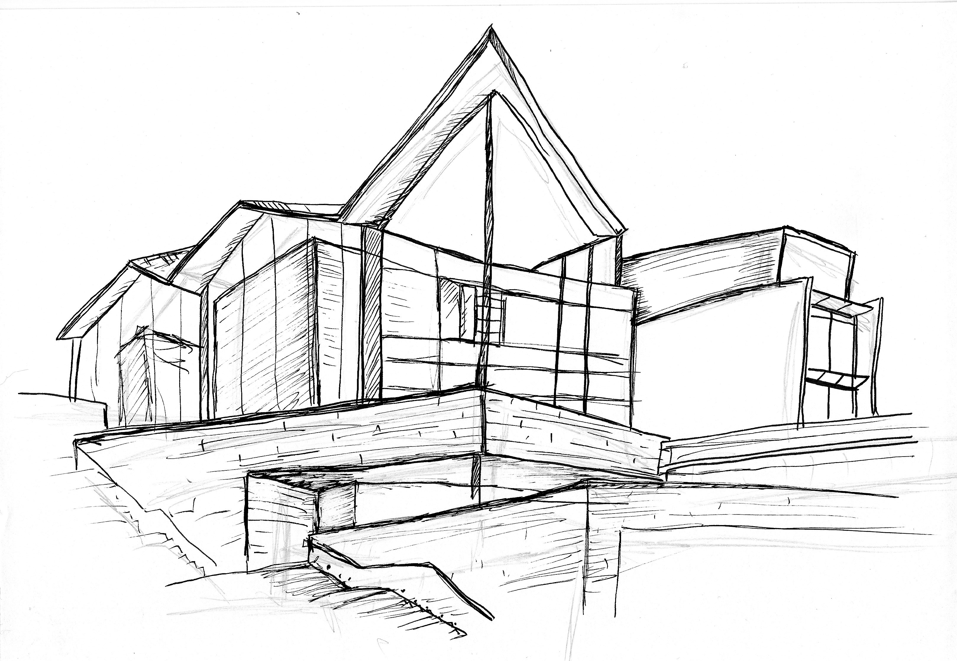
My second scamp is of the corner of the Winton Building, looking at it from the Café.
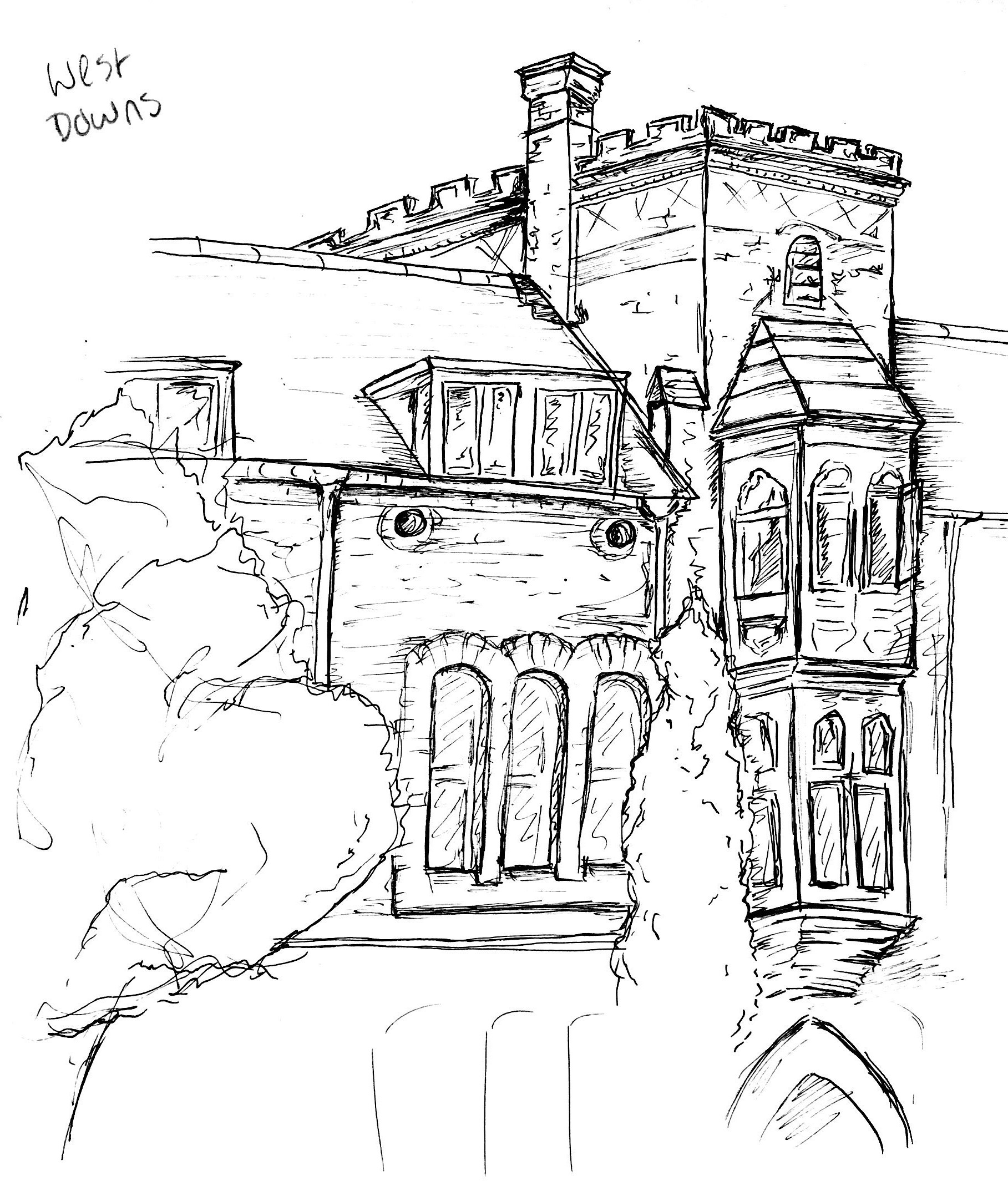
My third scamp is just above the main entrance of West Downs.
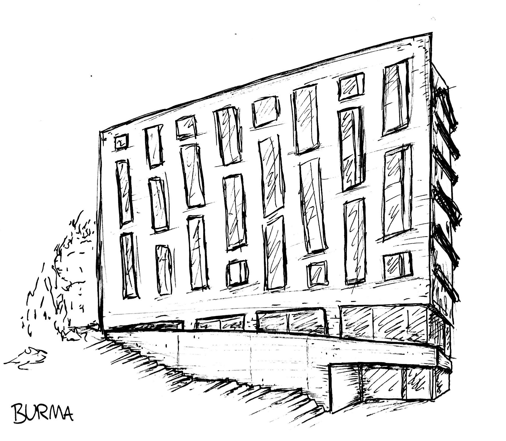
My fourth scamp is of the front of Burma road flats.
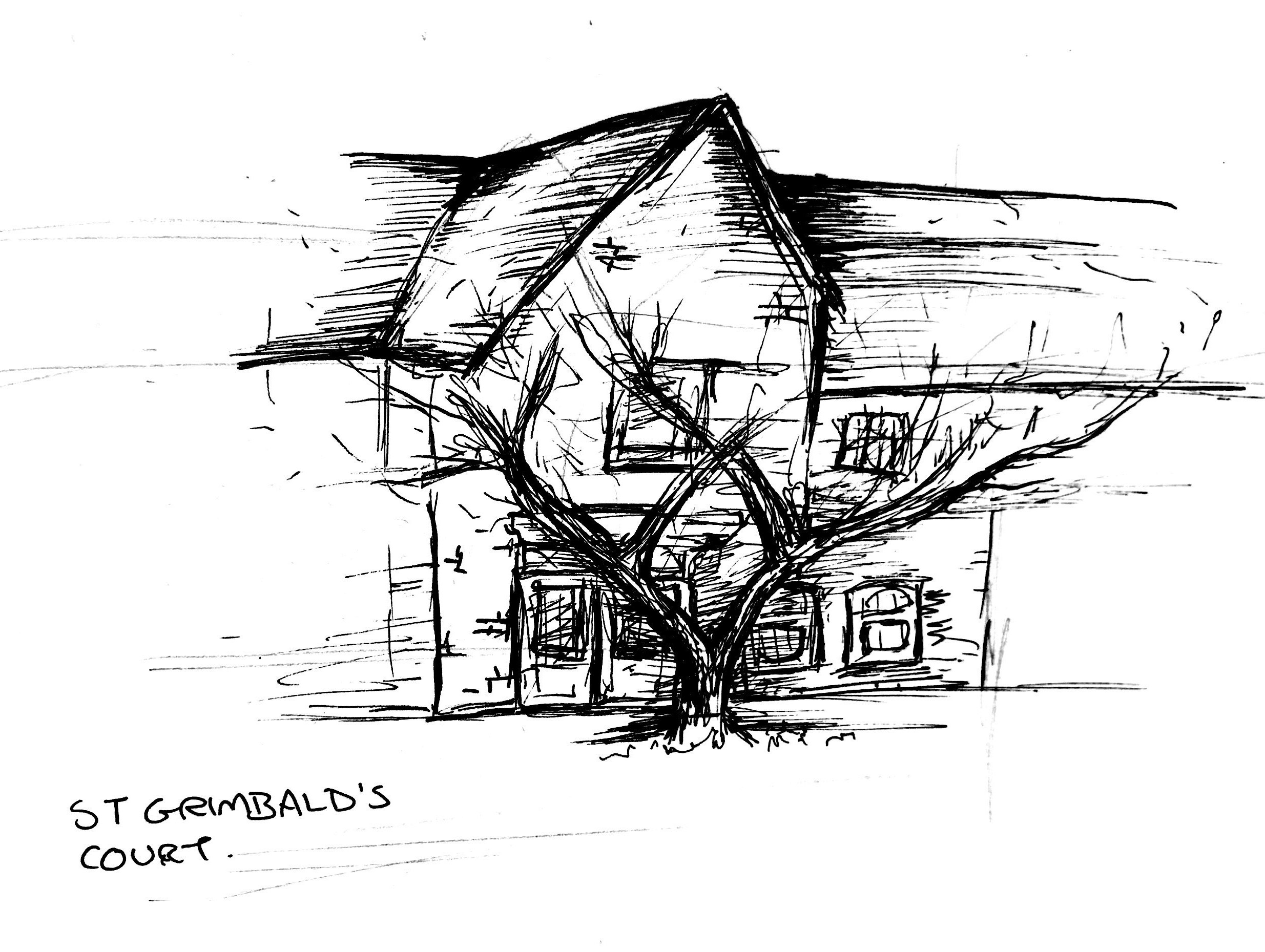
For my fifth and final scamp I decided to take even less time, around 5 minutes to see how it would look. I decided to try to draw St Grimbald’s Court. In the end I defiantly prefer my previous sketches that took just a little more time.
For our October break task, we were asked to draw scamps. Scamps are rough sketches that are relatively detailed but done quickly to grab a quick snapshot of an area. Our task required that we drew structures and areas from the University of Winchester campus. I drew two scamps of buildings on the Winchester campus.
I began by using a pencil to briefly outline the structures, then a 0.3mm fine liner to complete the drawings in a sketchy fast manner. None of the drawings took over 10 minutes to complete, therefore, they can be considered scamps.
My first scamp is of the King Alfred Building, looking up from the plaza area below.
My second scamp is of the corner of the Winton Building, looking at it from the Café.
My third scamp is just above the main entrance of West Downs.
My fourth scamp is of the front of Burma road flats.
For my fifth and final scamp I decided to take even less time, around 5 minutes to see how it would look. I decided to try to draw St Grimbald’s Court. In the end I defiantly prefer my previous sketches that took just a little more time.
 3D CAD Drawing
<
3D CAD Drawing
>
3D CAD Drawing
>
3D PC aided drawing (Sheet stuff)
3D CAD Drawing
Task One-UCS
For this task we were given a booklet of instructions to follow with the goal to able to create 3D objects. It started off easy but gradually got harder and harder as a booklet went on. It helps me to gradually begin to understand the first steps of 3D design.
The first thing we were asked to do was to play around the settings in the 3D window. This included figuring out what the UCS icon is as well as how to specify the direction of the x-axis so that you are drawing on the correct level. Whilst exploring the 3D part of the programme I decided to permanently change my background is white as for myself this makes the drawing clearer to see, I also remove the grid as I didn’t think it was needed for this exercise.
Task Two- Extruded planar, Loft and Surftrim We began the actual task by creating some layers. We were told to call them S1, S2, S3, and to use different colours for each one. This was so when we came to make the drawing 3D it was easy to differentiate which part was which.
The first thing we had to draw was a 3D box that looks like a rectangle with a bit sliced out of it. I did this by using the different layers and the different USC points to draw closed polygons for each side. For each side I had to change the UCS otherwise the lines would have all been drawn on the same level, for example they were all would have been flat if I left the settings on the bottom UCS. The shape had to be made up of closed polygons so that they could be manipulated easily further into the task. If they had been a polyline or singular lines I wouldn’t have been able to extrude or fill the shape.

Then came the difficult task of adding the triangle and the circles to the faces of the shape. I found this very difficult as it wasn’t obvious every single time which face all UCS I needed. This led me to a few times putting the shape onto the wrong area of the shape. To combat this issue, I ended up drawing a little sketch of the shape by hand and wrote out which UCS was for which side of the shape. This helped the task to run a lot smoother as I wasn’t constantly getting confused about which UCS to use. Using my little diagram, I managed to successfully but the circles and the triangle on the correct faces of the shape.

Now it was time to learn how to extrude. Extruding means to drag or pull a 2D object to make it 3D. A solid extrusion when used on a circle for example, means that when you pull the 2D circle the final cylinder has both a lid and a bottom. Where a surface extrusion means you only pull the outside, for example the circle doing a surface extrusion would make it look like a hula hoop. The first thing I had to do was change the extrude mode surface as the standard mode is solid but for this task we were only using surface. I needed to extrude the circle, so it was only the outside ring of the cylinder.
I extruded the circle from the bottom layer through the top layer of the 3D shape. This meant that I could subtract the part of the cylinder that overlaps the top layer so that the cylinder perfectly fits inside of the shape, instead of just trying to guess where to drag the circle up to. This makes the final version of the 3D objects look a little more polished and accurate.
The last part was to try a solid extrude on the triangle. To do this I pretty much did the same process as with the circle but instead of being a surface extrusion I had to change it to a solid extrusion. The only thing that was different with the two different shapes using the two different types of extrusion was that the triangle had a lid to it whereas the cylinder was hollow.

Task Three -Path Extrusion
The next task was to try out path extrusion. A path extrusion is as the name suggests, to take a line and use this to make a 3D shape. To do this I had to draw a rectangle on the floor or the bottom UCS, and then draw an arc from one of the corners of the rectangle upwards on the left UCS. This left me with a rectangle on the floor and an arc arching upwards away from the bottom.

To complete the path extrusion, all I had to do was when setting up and extrude as I did before I selected path. Doing this allowed me to select both the Ark and the rectangle to extrude from which made a wavelike shape.

This second task ended up being a lot easier than I expected to be. From the outlook it seemed rather complicated but realistically it was only two steps; drawing the 2D lines then extruding them.
Task Four-Taper Extrusion
The taper extrusion is dragging the object to make it 3D as before, but it instead of the line going straight, it will taper to a point. To try this out I had to draw a polygon with five sides using the polygon type command. By using the polygon type command, it made the 2D shape one object rather than five separate lights.
To perform the extrude, I had to type extrude as before but then click T for taper angle then selects a high at which I wanted to taper and then finally drag the polygon upwards until I was happy with the height. You can easily see as the polygon gains height it begins to shrink, so that if I dragged it high enough it would eventually taper to a point.

This is another part of the task that I found surprisingly easy. As before it is a lot more complicated than I first thought is.
Task Five - PRESSPULL
The aim of this task was to learn the difference between PRESSPULL and extrude. Extruding is the easiest way to make a flat object 3D but it can only be done on an object that is already a single entity, for example a polyline. Whereas PRESSPULL can be done on an object that has not been a single entity, or in other words are separate lines.
To test this out I copied two versions of the 3D extruded polygon that I had just used. I then selected one of the 3D polygons and typed PRESSPULL. Finally, I imputed 100 so that a polygon would be extruded upwards to the higher 100. The second polygon I selected it and then typed PRESSPULL but instead of inputting a number I just dragged it upwards to the high I wanted. In a situation where things must be exact, using the first method would be more applicable. But in a situation where it is just an idea of the design the second method would be just fine.

Task six-Mesh Modelling
This task was just a case of experimenting using the smooth settings. For my experimentation I decided to use spheres. I made three different spheres using the sphere tool, they are all different sizes and widths. I then selected each shape separately and played around in different variations with the smooth tool making some shapes smoother than others to see what happens. In conclusion the smooth tool converts a sphere from a solid 3D object into a mesh 3D object and then smooths out all the corners.

This was a fun brief activity that showed some of the cool things that CAD can do.
Task seven-revolve and NURBS
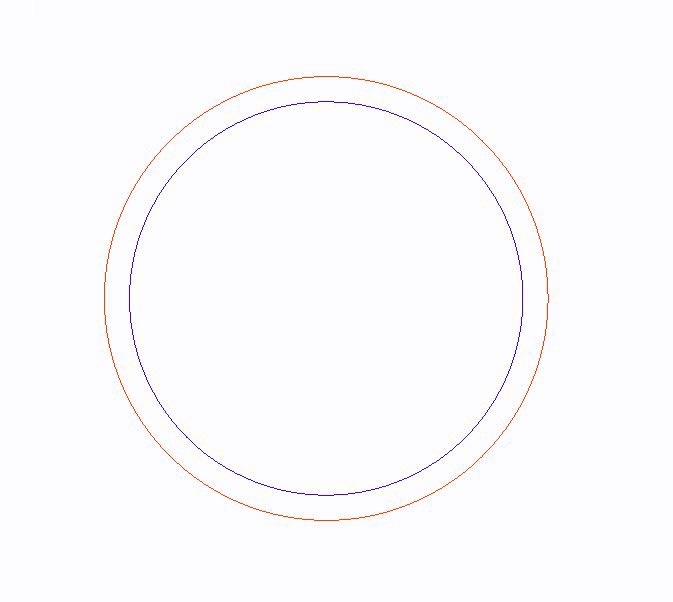
For this task were given a diagram within the booklet to copy. Again, I needed two different layers a red one and a blue one. This is just to make the second part a little easier. To copy the diagram, I had to use closed polylines and they had to be the correct lengths.
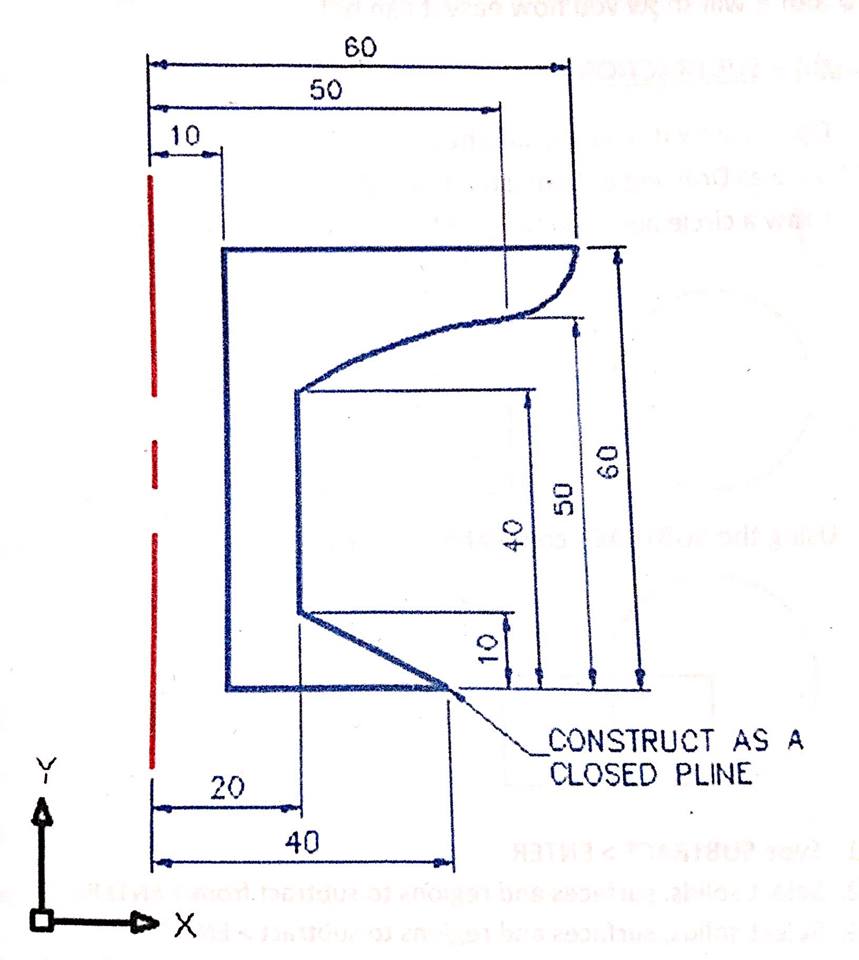
Once all the lines were drawn, I had to use the revolve command. To do this I selected the shape as well as the guideline to the left of it. I then types the command revolve and set it to 360. This meant that the shape revolve 360° around the guideline. If I had written hundred and 80 instead the shape would have only revolved halfway round the guideline not entirely.

I next needed to convert the shape into NURBS. This stands for non-uniform national basis spline. They offer great precision and flexibility for model shapes however, once it’s been converted they can never convert back.
To convert my objects had to selected and then type in the command box NURBS. Now that each section has a separate element I was able to select the top of the object and extrude upwards to create more of a wine glass like shape.

This exercise really helped me to see what can be done within 3D. CAD 3D is not just making a box, you can make a lot more than I originally thought you could.
Task One-UCS
For this task we were given a booklet of instructions to follow with the goal to able to create 3D objects. It started off easy but gradually got harder and harder as a booklet went on. It helps me to gradually begin to understand the first steps of 3D design.
The first thing we were asked to do was to play around the settings in the 3D window. This included figuring out what the UCS icon is as well as how to specify the direction of the x-axis so that you are drawing on the correct level. Whilst exploring the 3D part of the programme I decided to permanently change my background is white as for myself this makes the drawing clearer to see, I also remove the grid as I didn’t think it was needed for this exercise.
Task Two- Extruded planar, Loft and Surftrim We began the actual task by creating some layers. We were told to call them S1, S2, S3, and to use different colours for each one. This was so when we came to make the drawing 3D it was easy to differentiate which part was which.
The first thing we had to draw was a 3D box that looks like a rectangle with a bit sliced out of it. I did this by using the different layers and the different USC points to draw closed polygons for each side. For each side I had to change the UCS otherwise the lines would have all been drawn on the same level, for example they were all would have been flat if I left the settings on the bottom UCS. The shape had to be made up of closed polygons so that they could be manipulated easily further into the task. If they had been a polyline or singular lines I wouldn’t have been able to extrude or fill the shape.
Then came the difficult task of adding the triangle and the circles to the faces of the shape. I found this very difficult as it wasn’t obvious every single time which face all UCS I needed. This led me to a few times putting the shape onto the wrong area of the shape. To combat this issue, I ended up drawing a little sketch of the shape by hand and wrote out which UCS was for which side of the shape. This helped the task to run a lot smoother as I wasn’t constantly getting confused about which UCS to use. Using my little diagram, I managed to successfully but the circles and the triangle on the correct faces of the shape.
Now it was time to learn how to extrude. Extruding means to drag or pull a 2D object to make it 3D. A solid extrusion when used on a circle for example, means that when you pull the 2D circle the final cylinder has both a lid and a bottom. Where a surface extrusion means you only pull the outside, for example the circle doing a surface extrusion would make it look like a hula hoop. The first thing I had to do was change the extrude mode surface as the standard mode is solid but for this task we were only using surface. I needed to extrude the circle, so it was only the outside ring of the cylinder.
I extruded the circle from the bottom layer through the top layer of the 3D shape. This meant that I could subtract the part of the cylinder that overlaps the top layer so that the cylinder perfectly fits inside of the shape, instead of just trying to guess where to drag the circle up to. This makes the final version of the 3D objects look a little more polished and accurate.
The last part was to try a solid extrude on the triangle. To do this I pretty much did the same process as with the circle but instead of being a surface extrusion I had to change it to a solid extrusion. The only thing that was different with the two different shapes using the two different types of extrusion was that the triangle had a lid to it whereas the cylinder was hollow.
Task Three -Path Extrusion
The next task was to try out path extrusion. A path extrusion is as the name suggests, to take a line and use this to make a 3D shape. To do this I had to draw a rectangle on the floor or the bottom UCS, and then draw an arc from one of the corners of the rectangle upwards on the left UCS. This left me with a rectangle on the floor and an arc arching upwards away from the bottom.
To complete the path extrusion, all I had to do was when setting up and extrude as I did before I selected path. Doing this allowed me to select both the Ark and the rectangle to extrude from which made a wavelike shape.
This second task ended up being a lot easier than I expected to be. From the outlook it seemed rather complicated but realistically it was only two steps; drawing the 2D lines then extruding them.
Task Four-Taper Extrusion
The taper extrusion is dragging the object to make it 3D as before, but it instead of the line going straight, it will taper to a point. To try this out I had to draw a polygon with five sides using the polygon type command. By using the polygon type command, it made the 2D shape one object rather than five separate lights.
To perform the extrude, I had to type extrude as before but then click T for taper angle then selects a high at which I wanted to taper and then finally drag the polygon upwards until I was happy with the height. You can easily see as the polygon gains height it begins to shrink, so that if I dragged it high enough it would eventually taper to a point.
This is another part of the task that I found surprisingly easy. As before it is a lot more complicated than I first thought is.
Task Five - PRESSPULL
The aim of this task was to learn the difference between PRESSPULL and extrude. Extruding is the easiest way to make a flat object 3D but it can only be done on an object that is already a single entity, for example a polyline. Whereas PRESSPULL can be done on an object that has not been a single entity, or in other words are separate lines.
To test this out I copied two versions of the 3D extruded polygon that I had just used. I then selected one of the 3D polygons and typed PRESSPULL. Finally, I imputed 100 so that a polygon would be extruded upwards to the higher 100. The second polygon I selected it and then typed PRESSPULL but instead of inputting a number I just dragged it upwards to the high I wanted. In a situation where things must be exact, using the first method would be more applicable. But in a situation where it is just an idea of the design the second method would be just fine.
Task six-Mesh Modelling
This task was just a case of experimenting using the smooth settings. For my experimentation I decided to use spheres. I made three different spheres using the sphere tool, they are all different sizes and widths. I then selected each shape separately and played around in different variations with the smooth tool making some shapes smoother than others to see what happens. In conclusion the smooth tool converts a sphere from a solid 3D object into a mesh 3D object and then smooths out all the corners.
This was a fun brief activity that showed some of the cool things that CAD can do.
Task seven-revolve and NURBS
For this task were given a diagram within the booklet to copy. Again, I needed two different layers a red one and a blue one. This is just to make the second part a little easier. To copy the diagram, I had to use closed polylines and they had to be the correct lengths.
Once all the lines were drawn, I had to use the revolve command. To do this I selected the shape as well as the guideline to the left of it. I then types the command revolve and set it to 360. This meant that the shape revolve 360° around the guideline. If I had written hundred and 80 instead the shape would have only revolved halfway round the guideline not entirely.
I next needed to convert the shape into NURBS. This stands for non-uniform national basis spline. They offer great precision and flexibility for model shapes however, once it’s been converted they can never convert back.
To convert my objects had to selected and then type in the command box NURBS. Now that each section has a separate element I was able to select the top of the object and extrude upwards to create more of a wine glass like shape.
This exercise really helped me to see what can be done within 3D. CAD 3D is not just making a box, you can make a lot more than I originally thought you could.
 Multi-discipline Computer Aided Drawing
<
Multi-discipline Computer Aided Drawing
Multi-discipline computer aided drawing
This task consisted of making three different 3D models each for different disciplines. We could choose any object that relates to the three disciplines we choose. I decided on Landscaping (BBQ), Plumbing (Pipe) and Structural (H beam).
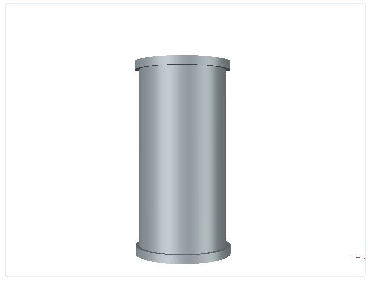
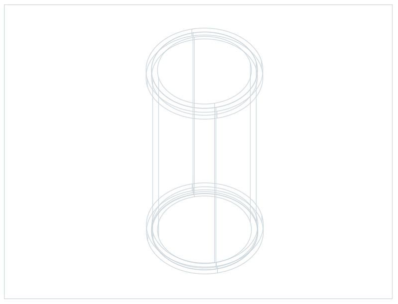
I first decided to make the plumbing pipe. To do this, I started by drawing two circles one larger than the other. I then extruded the inner circle to 500, and the outer circle to 400. I extruded the two circles to different heights so that when it came to subtract one from the other to make them hollow, it was easier to select the correct circles.
Once I had a thick, hollow cylinder I had to make two more shorter ones. To do this, I did the same process of making two circles of different sizes and extruding to different heights. This time I extruded to a much shorter height of 50. I then copied a second cylinder and dragged it upwards so there was one on each end. This helped to made it look more like a pipe.
Below I have displayed the finished 3D model in a rendered style and also as a 2D wireframe image.
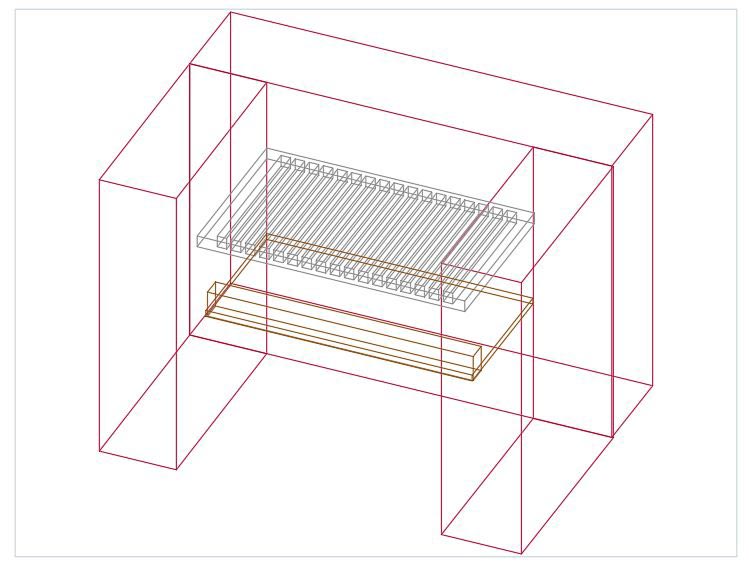
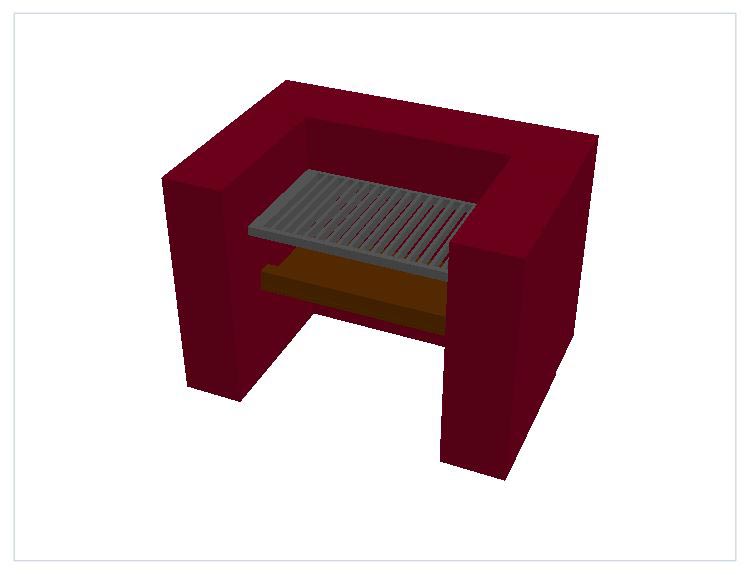
For my next model I decided to make a BBQ.
To make the BBQ walls was rather simple. I made three 2D rectangles, one large one and two smaller ones at the ends of the smaller one. I then selected all three and extruded them to a height of 150.
The hardest part was the grill. To make the grill I made another 2D rectangle in the middle area between the previous ones. I then made a very thin rectangle on the left of the new rectangle. To multiply that smaller rectangle in a straight line horizontally along the grill I needed to use the rectangle array tool. I selected the tool and made it have 13 columns but only one row so that I had one long row from one side of the grill to the other.
The next part was to make the grill 3D. I started by exploding the small rectangles. I had to do this as when I used the rectangular array they automatically became a single object. I next selected all of the small rectangles again and extruded them to a height of 20. I then selected the large grill rectangle and extruded to a height of 10. To make the gaps all I had to do was subtract the small rectangles from the larger one, which is exactly what I did.
The last step for the grill was to drag the newly made grill to the desired height.
The final thing to make was the coal tray. This one was as simple to make as the original walls. All I had to do was make two rectangles, a large one and a thin horizontal one where I wanted the lip. I then extruded the thin rectangle to 40 and the bigger one to 10. This meant I had a kind of tray with a lip.
To finish the BBQ off, I dragged the coal try upwards to the desired height and coloured the drawing.
Below you can see the finished BBQ, first in 2D wireframe form and secondly in a rendered image.
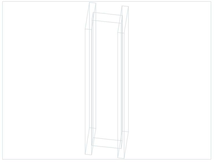
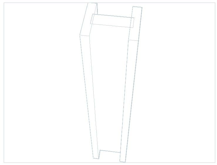
The final item I needed to make was the H Frame. I decided to make a H frame as it’s the first thing to come to mind when I think of structural support.
Out of all of the objects the H frame was the easiest to create. It comprised of only three rectangles. One slightly longer one in the middle and two shorter ones either end, in a H shape. Hence the name ‘H-frame’.
To make the frame I simply selected all the rectangles and extruded them all to a height of 300. I also made sure that the layer colour was grey, so it looked like metal.
Below is the finished model. First as a 2D wire frame, and then secondly as a hidden line image.
For my first attempt at making multiple 3D objects from nothing, I am really pleased with how they all came out- especially the BBQ. The only thing I would have wanted to do to improve was create other more detailed objects. But that is a task for another time.
This task consisted of making three different 3D models each for different disciplines. We could choose any object that relates to the three disciplines we choose. I decided on Landscaping (BBQ), Plumbing (Pipe) and Structural (H beam).
I first decided to make the plumbing pipe. To do this, I started by drawing two circles one larger than the other. I then extruded the inner circle to 500, and the outer circle to 400. I extruded the two circles to different heights so that when it came to subtract one from the other to make them hollow, it was easier to select the correct circles.
Once I had a thick, hollow cylinder I had to make two more shorter ones. To do this, I did the same process of making two circles of different sizes and extruding to different heights. This time I extruded to a much shorter height of 50. I then copied a second cylinder and dragged it upwards so there was one on each end. This helped to made it look more like a pipe.
Below I have displayed the finished 3D model in a rendered style and also as a 2D wireframe image.
For my next model I decided to make a BBQ.
To make the BBQ walls was rather simple. I made three 2D rectangles, one large one and two smaller ones at the ends of the smaller one. I then selected all three and extruded them to a height of 150.
The hardest part was the grill. To make the grill I made another 2D rectangle in the middle area between the previous ones. I then made a very thin rectangle on the left of the new rectangle. To multiply that smaller rectangle in a straight line horizontally along the grill I needed to use the rectangle array tool. I selected the tool and made it have 13 columns but only one row so that I had one long row from one side of the grill to the other.
The next part was to make the grill 3D. I started by exploding the small rectangles. I had to do this as when I used the rectangular array they automatically became a single object. I next selected all of the small rectangles again and extruded them to a height of 20. I then selected the large grill rectangle and extruded to a height of 10. To make the gaps all I had to do was subtract the small rectangles from the larger one, which is exactly what I did.
The last step for the grill was to drag the newly made grill to the desired height.
The final thing to make was the coal tray. This one was as simple to make as the original walls. All I had to do was make two rectangles, a large one and a thin horizontal one where I wanted the lip. I then extruded the thin rectangle to 40 and the bigger one to 10. This meant I had a kind of tray with a lip.
To finish the BBQ off, I dragged the coal try upwards to the desired height and coloured the drawing.
Below you can see the finished BBQ, first in 2D wireframe form and secondly in a rendered image.
The final item I needed to make was the H Frame. I decided to make a H frame as it’s the first thing to come to mind when I think of structural support.
Out of all of the objects the H frame was the easiest to create. It comprised of only three rectangles. One slightly longer one in the middle and two shorter ones either end, in a H shape. Hence the name ‘H-frame’.
To make the frame I simply selected all the rectangles and extruded them all to a height of 300. I also made sure that the layer colour was grey, so it looked like metal.
Below is the finished model. First as a 2D wire frame, and then secondly as a hidden line image.
For my first attempt at making multiple 3D objects from nothing, I am really pleased with how they all came out- especially the BBQ. The only thing I would have wanted to do to improve was create other more detailed objects. But that is a task for another time.
 Sketching and Storyboarding Game Environment
<
Sketching And Storyboarding Game Environment
Sketching and Storyboarding Game Environment
In this lesson, we were taught for the first time how to use Revit. Revit is another Autodesk program, but it is primarily used by architects and designers relating to building design. It’s easier than CAD to understand but there’s a lot more principles to figure out. At this stage, we only learnt the basics.
The main objective of this task was to create an environment for our group games within Revit. As my game was going to be a flat Super Mario esc game this task became rather difficult; but I decided to take the approach of what the game might have looked like if it was first person.
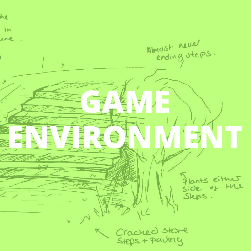
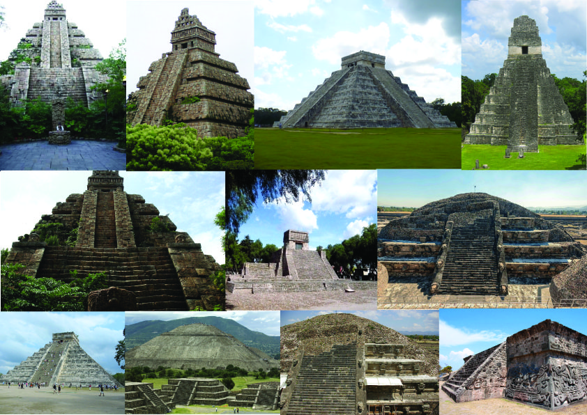
The main premise of the first level of my groups game was the Aztec era. To gain more insight into what I could create I did a little research on Aztec temples in the form of a mood board.
After looking at real Aztec temples I decided to base my scene at the bottom of the steps of a temple. To decide on the composition of the scene that I wanted to create in Revit, I drew a rough sketch of my potential scene.
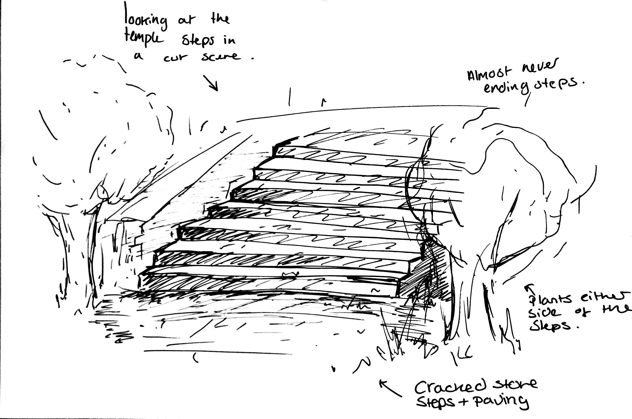
I decided to sketch a view from the bottom of the temple steps looking upwards. These temple steps would need to be made from stone as that was the primary material that the Aztecs used to build their temples. Due to the Aztecs residing in South America, I thought it only suitable that a lot of trees and shrubbery were included.
To make the scene in Revit I decided to use a staircase to make the temple as this was the closest I could get to the big brick block stairs of the Aztec temples. I inserted the staircase at the end of a rectangle room so that there was space to add other items. The final addition was the shrubbery. I decided on four larger trees furthest away from the stairs and them two smaller shrubs either side. My final choice was to make the stairs, wall and floor stone brick again to keep with the Aztec Temple theme as the temples where always made from stone.
Below is a Birdseye view of the final layout of the scene.

I concluded that if we were to use this scene in the game for anything, it would be for a cut scene within the game. The idea was that the brief cut scene would show the main character looking up the stairs of the temple upwards to wards the top. To show this, I attempted to take camera view screenshots in line view and as rendered images.
Below are the results.


The scene looks as I planned it to, and I am happy with the result. As my first attempt at using Revit I am glad about the outcome of the scene. The only thing that I would like to improve is the lighting. I wasn’t sure how to move it, but its current position does give a sense of mystery which adds to the atmosphere of the scene.
In this lesson, we were taught for the first time how to use Revit. Revit is another Autodesk program, but it is primarily used by architects and designers relating to building design. It’s easier than CAD to understand but there’s a lot more principles to figure out. At this stage, we only learnt the basics.
The main objective of this task was to create an environment for our group games within Revit. As my game was going to be a flat Super Mario esc game this task became rather difficult; but I decided to take the approach of what the game might have looked like if it was first person.
The main premise of the first level of my groups game was the Aztec era. To gain more insight into what I could create I did a little research on Aztec temples in the form of a mood board.
After looking at real Aztec temples I decided to base my scene at the bottom of the steps of a temple. To decide on the composition of the scene that I wanted to create in Revit, I drew a rough sketch of my potential scene.
I decided to sketch a view from the bottom of the temple steps looking upwards. These temple steps would need to be made from stone as that was the primary material that the Aztecs used to build their temples. Due to the Aztecs residing in South America, I thought it only suitable that a lot of trees and shrubbery were included.
To make the scene in Revit I decided to use a staircase to make the temple as this was the closest I could get to the big brick block stairs of the Aztec temples. I inserted the staircase at the end of a rectangle room so that there was space to add other items. The final addition was the shrubbery. I decided on four larger trees furthest away from the stairs and them two smaller shrubs either side. My final choice was to make the stairs, wall and floor stone brick again to keep with the Aztec Temple theme as the temples where always made from stone.
Below is a Birdseye view of the final layout of the scene.
I concluded that if we were to use this scene in the game for anything, it would be for a cut scene within the game. The idea was that the brief cut scene would show the main character looking up the stairs of the temple upwards to wards the top. To show this, I attempted to take camera view screenshots in line view and as rendered images.
Below are the results.
The scene looks as I planned it to, and I am happy with the result. As my first attempt at using Revit I am glad about the outcome of the scene. The only thing that I would like to improve is the lighting. I wasn’t sure how to move it, but its current position does give a sense of mystery which adds to the atmosphere of the scene.
 3D Game Logo
<
3D Game Logo
3D logo for game
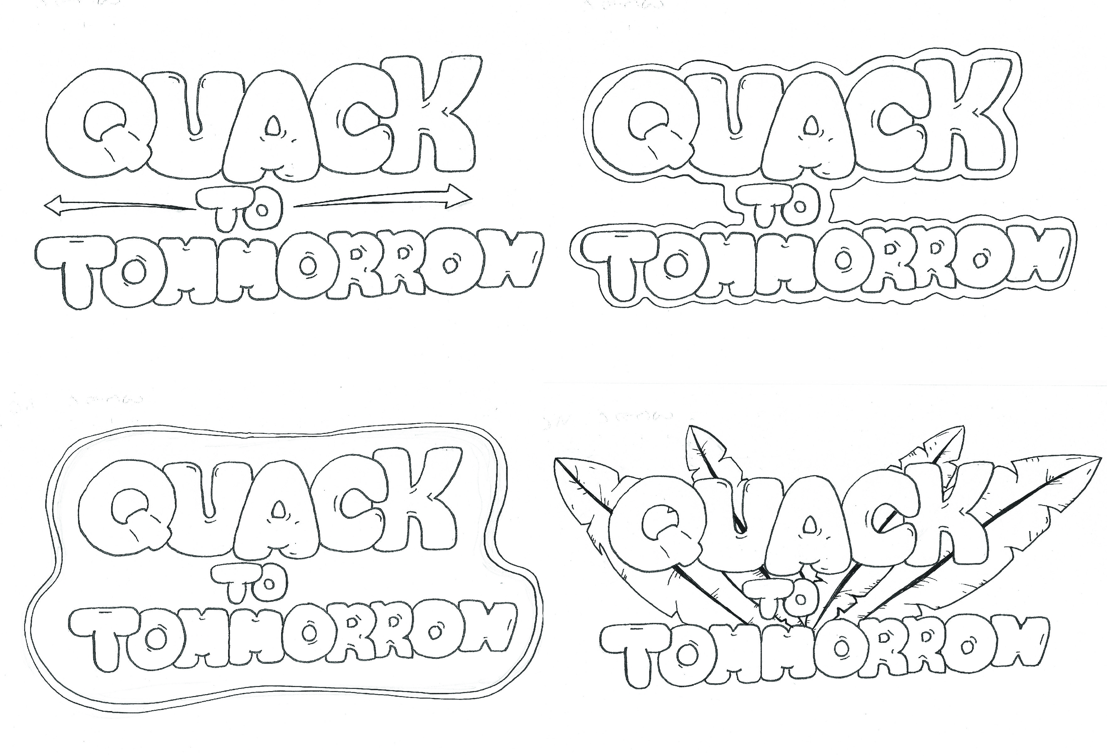
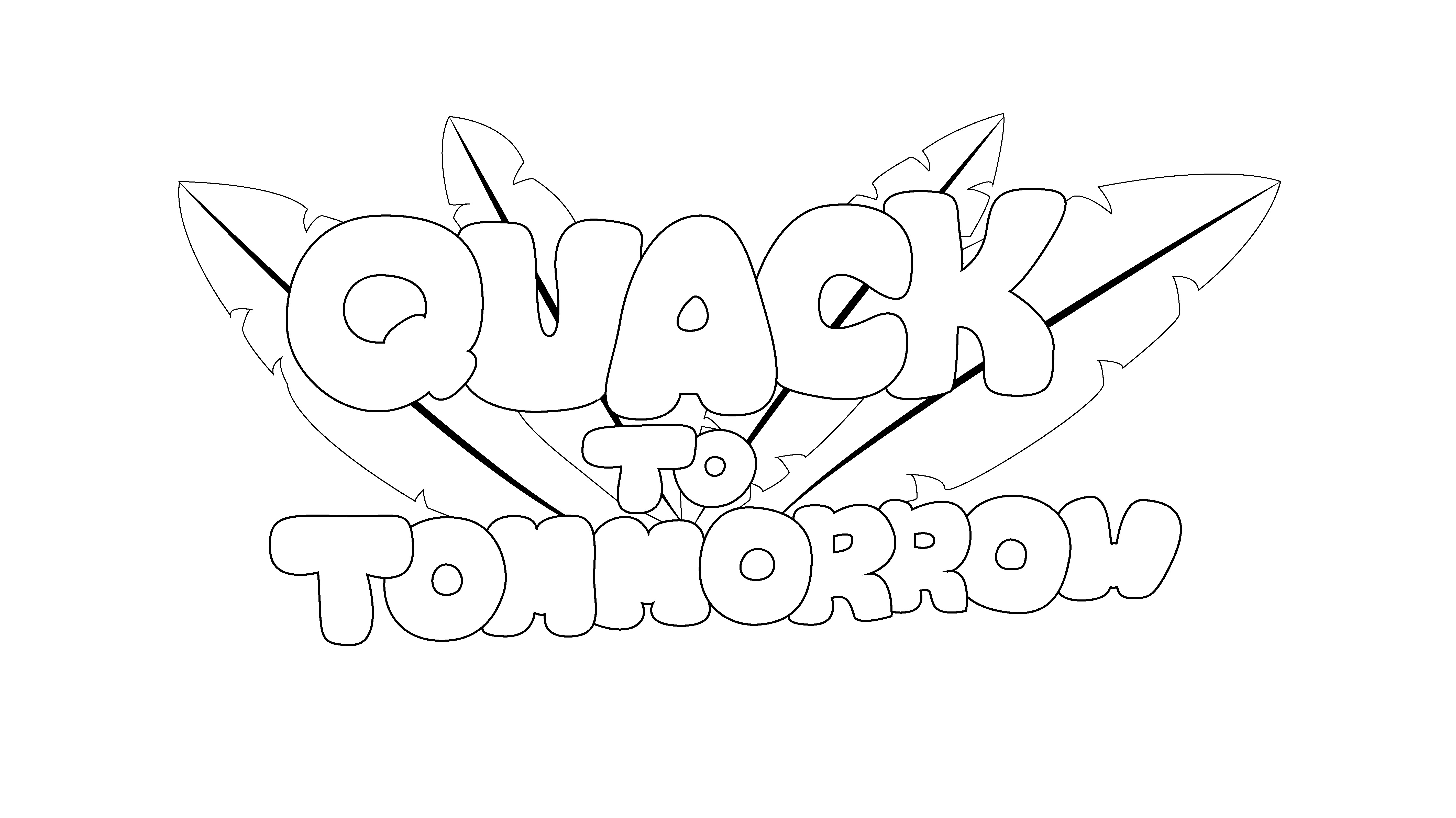
As my game group already had a logo design, I decided to do a redesign of the original and make it more fun and cartoonish. I started off by doing a few sketches, experimenting with fun bubble writing and slightly more serious lined text. I decided on the bubble text as it seemed more fun and relates more to the 11-15 year olds brief for the game project.
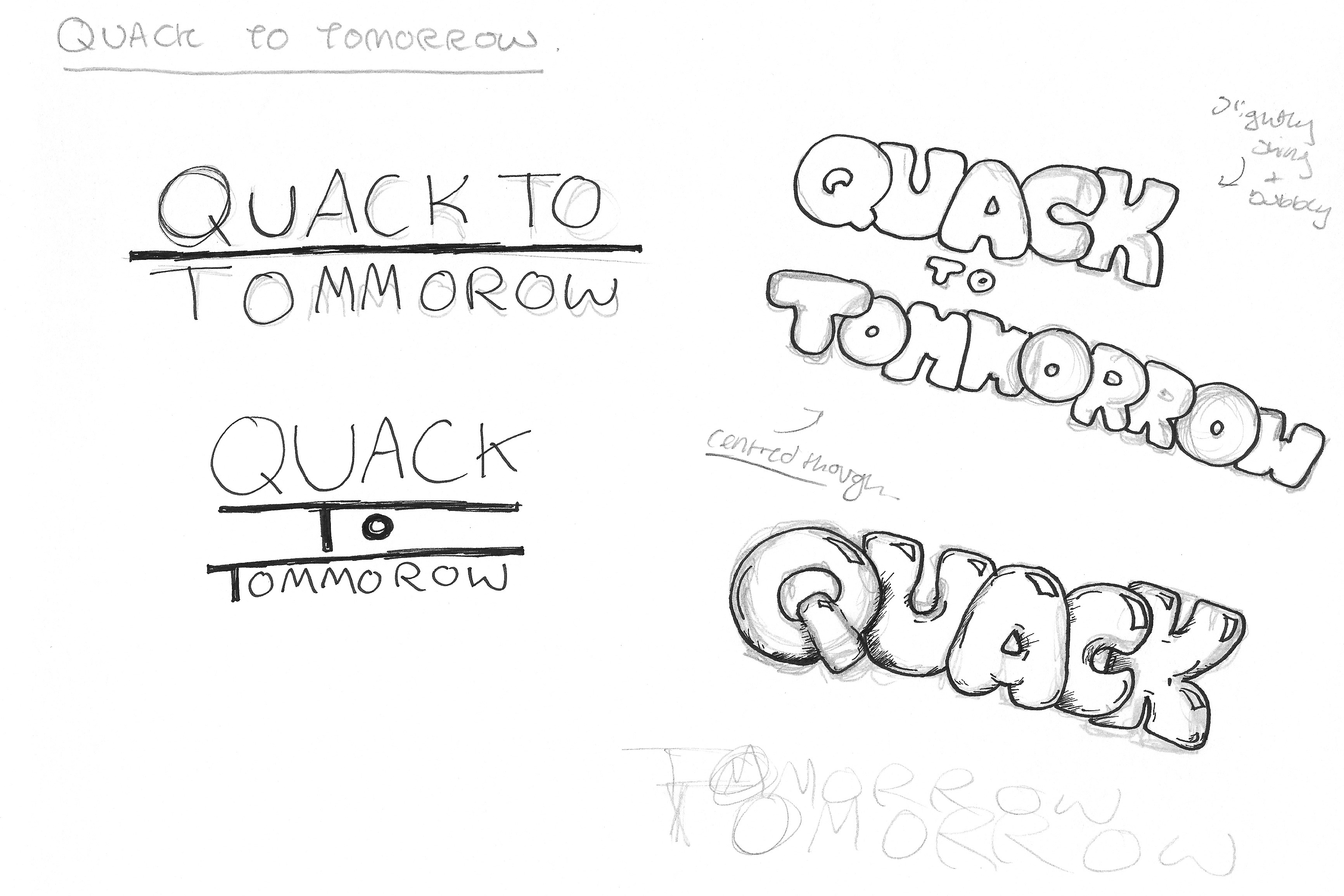
Once I drew out the design and decided on the text layout, I wanted to experiment in adding extra accessories to the logo. I tried outlines, arrows and feathers (that relate to the duck aspect of the game) in different arrangements around the text. have decided on the feathers as they really make the logo stand out from the crowd and straight away allow the player to know about the bird aspect. They also help link to the first level of the game, the Aztecs, as they seem almost like a feather headdress.
Once I had decided on a drawing, I scanned the drawing and put it into illustrator. I used the pen tool to outline the drawing by tracing over the scanned image. I did this in a bright pink colour so that the new lines are easier to see. I then deleted the image so that I was left with only the new line drawing that I had just created.


My next job was to make each letter solid and sort out any mistakes- ie. Wobbly lines, line gaps and line weights. This all helps to make the finished look generally better and more put together. Once everything had been adjusted I was able to export the final 2D logo as a finished design.

To start making the 2D logo 3D I began by inserting the drawn version into AutoCAD. I did this so that I would be able to trace the lines using the polyline tool alternating between arcs and lines. It just helped to make the letters a little more accurate to the original drawing. When drawing the lines, I used two different layers. One layer in red for the text and a second layer in green for the feathers/leaves. This is to make it easy to differentiate which lines are which.


The first stage to make the logo 3D was to extrude the middle section of some of the letters. For example, the letter ‘O’ and ‘Q’. When I extruded the middle parts I extruded them to a height of 300, and when I extruded the outer parts of the letters I did this to a height of 250. The middle had to be taller than the outside as I had to subtract it from the outer to create the hole in the middle. If the middle was shorter it would have been impossible to make a hole all the way through the letter.


The next stage was to extrude the feathers/leaves. When I extruded the feathers/leaves I extruded them to a height of 200, so slightly smaller than the text. This was so there is an easy difference between the heights. The text needed to be taller as it is the most important part and needs to be on top.

As a bit of an experiment I decided to try to smooth the logo out. To do this the letters all had to be converted to mesh objects. I only smoothed the feathers/leaves once, where as I smoothed the letters to the highest level of 4. I think that smoothing them did help make the logo look more 3D, but it also highlighted the different letter sizes which lowered the quality of the logo.

All in all I think that the logo looks better when it was not smoothed but the smoothing did help to add an extra dimension to it.
As my game group already had a logo design, I decided to do a redesign of the original and make it more fun and cartoonish. I started off by doing a few sketches, experimenting with fun bubble writing and slightly more serious lined text. I decided on the bubble text as it seemed more fun and relates more to the 11-15 year olds brief for the game project.
Once I drew out the design and decided on the text layout, I wanted to experiment in adding extra accessories to the logo. I tried outlines, arrows and feathers (that relate to the duck aspect of the game) in different arrangements around the text. have decided on the feathers as they really make the logo stand out from the crowd and straight away allow the player to know about the bird aspect. They also help link to the first level of the game, the Aztecs, as they seem almost like a feather headdress.
Once I had decided on a drawing, I scanned the drawing and put it into illustrator. I used the pen tool to outline the drawing by tracing over the scanned image. I did this in a bright pink colour so that the new lines are easier to see. I then deleted the image so that I was left with only the new line drawing that I had just created.
My next job was to make each letter solid and sort out any mistakes- ie. Wobbly lines, line gaps and line weights. This all helps to make the finished look generally better and more put together. Once everything had been adjusted I was able to export the final 2D logo as a finished design.
To start making the 2D logo 3D I began by inserting the drawn version into AutoCAD. I did this so that I would be able to trace the lines using the polyline tool alternating between arcs and lines. It just helped to make the letters a little more accurate to the original drawing. When drawing the lines, I used two different layers. One layer in red for the text and a second layer in green for the feathers/leaves. This is to make it easy to differentiate which lines are which.
The first stage to make the logo 3D was to extrude the middle section of some of the letters. For example, the letter ‘O’ and ‘Q’. When I extruded the middle parts I extruded them to a height of 300, and when I extruded the outer parts of the letters I did this to a height of 250. The middle had to be taller than the outside as I had to subtract it from the outer to create the hole in the middle. If the middle was shorter it would have been impossible to make a hole all the way through the letter.
The next stage was to extrude the feathers/leaves. When I extruded the feathers/leaves I extruded them to a height of 200, so slightly smaller than the text. This was so there is an easy difference between the heights. The text needed to be taller as it is the most important part and needs to be on top.
As a bit of an experiment I decided to try to smooth the logo out. To do this the letters all had to be converted to mesh objects. I only smoothed the feathers/leaves once, where as I smoothed the letters to the highest level of 4. I think that smoothing them did help make the logo look more 3D, but it also highlighted the different letter sizes which lowered the quality of the logo.
All in all I think that the logo looks better when it was not smoothed but the smoothing did help to add an extra dimension to it.
GAME PROJECT
 Game Project Logo
<
Game Project Logo
Game Logo Design
As with any game, our game needed a logo. The logo is the first point of call. It has to be recognisable and simple yet still represent the game. Within my group, I decided to take on the task of making the logo.
To create the initial log for our game I looked at references including the ‘Back to the future’ logo, and generally 1950’s themed logos to stay with the concept. I liked the layout of the ‘Back to the future’ logo as it is compact yet clear and gives a sense of movement.
Looking at the 50’s styled logos I liked the fluidness of the text and wanted to incorporate that by using a serif font with a vintage kind of feel. I decided to merge a few fonts together and use the pen tool in illustrator to trace them to create my own kind of font. I ended up with a fluid font that is still clear and easy to read.
To bring the font together I decided on a right-side paragraph alignment. I also decided to overlay two layers of the text to make it seem ever so slightly 3D. To complete the logo, I added three right aligned lines, evenly spaced, which I felt echoed a little bit of 1950-50 art deco design which used a lot of line work.
 Character Design
<
Character Design
Character Design
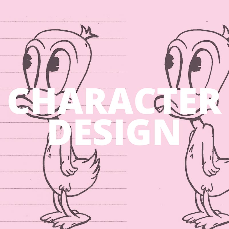
Within my game group I was the lead character designer. I designed the two lead characters and the main boss of the game.
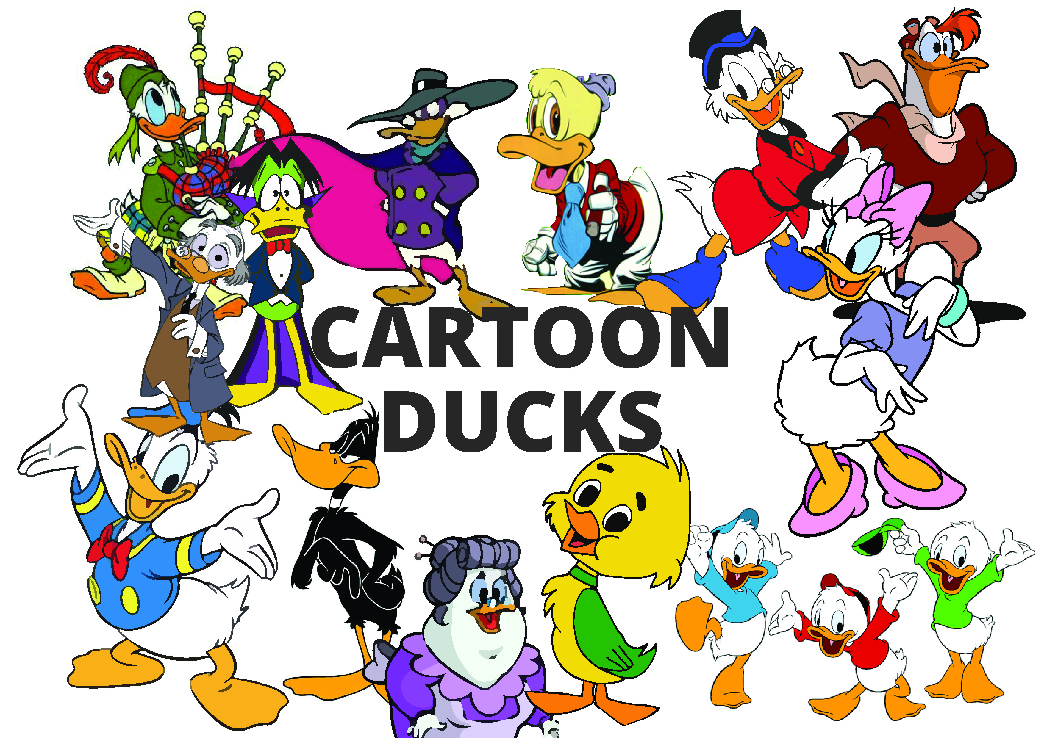
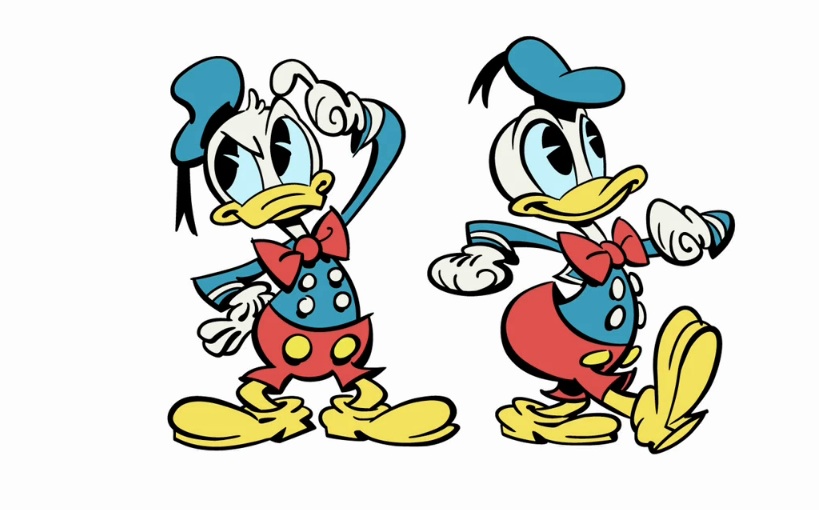
To begin the design process, I started by creating a mood board that contained a selection of images of famous cartoon ducks. The verity contained ducks such as ‘Scrooge McDuck’, ‘Donald Duck’, ‘Count Quackula’ and many more. I decided on the Disney esc design. This was due to the friendliness of the design with the smooth lines and bright yet not extravagant colouring.
For the core design of the ducks I looked a lot at the Donald duck design from the ‘Mickey Mouse’ TV series. It stuck out as it still has the traditional design but seemed a little retro with the line work. The varying line weights and the solid yet memorable colourings add to this.
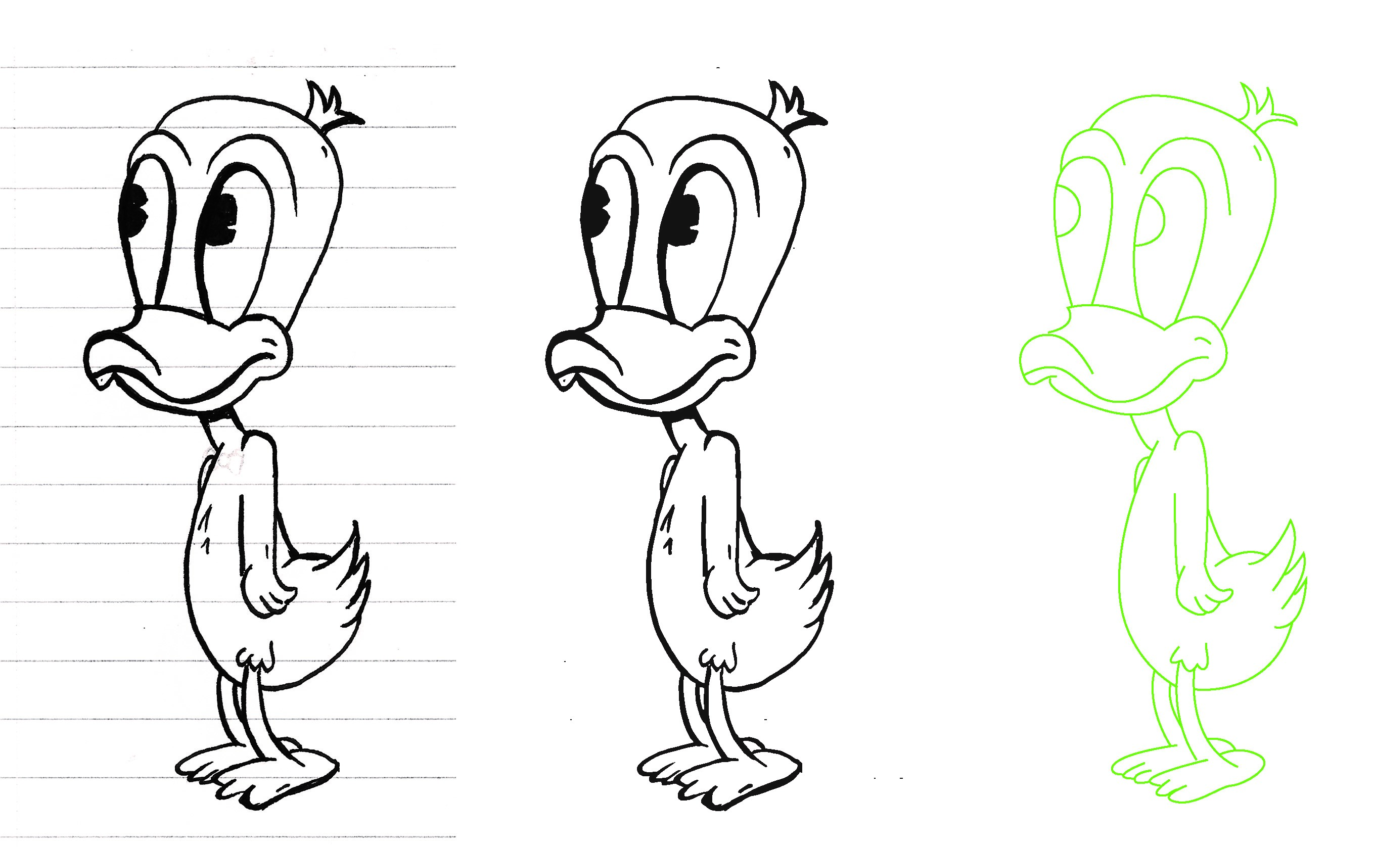
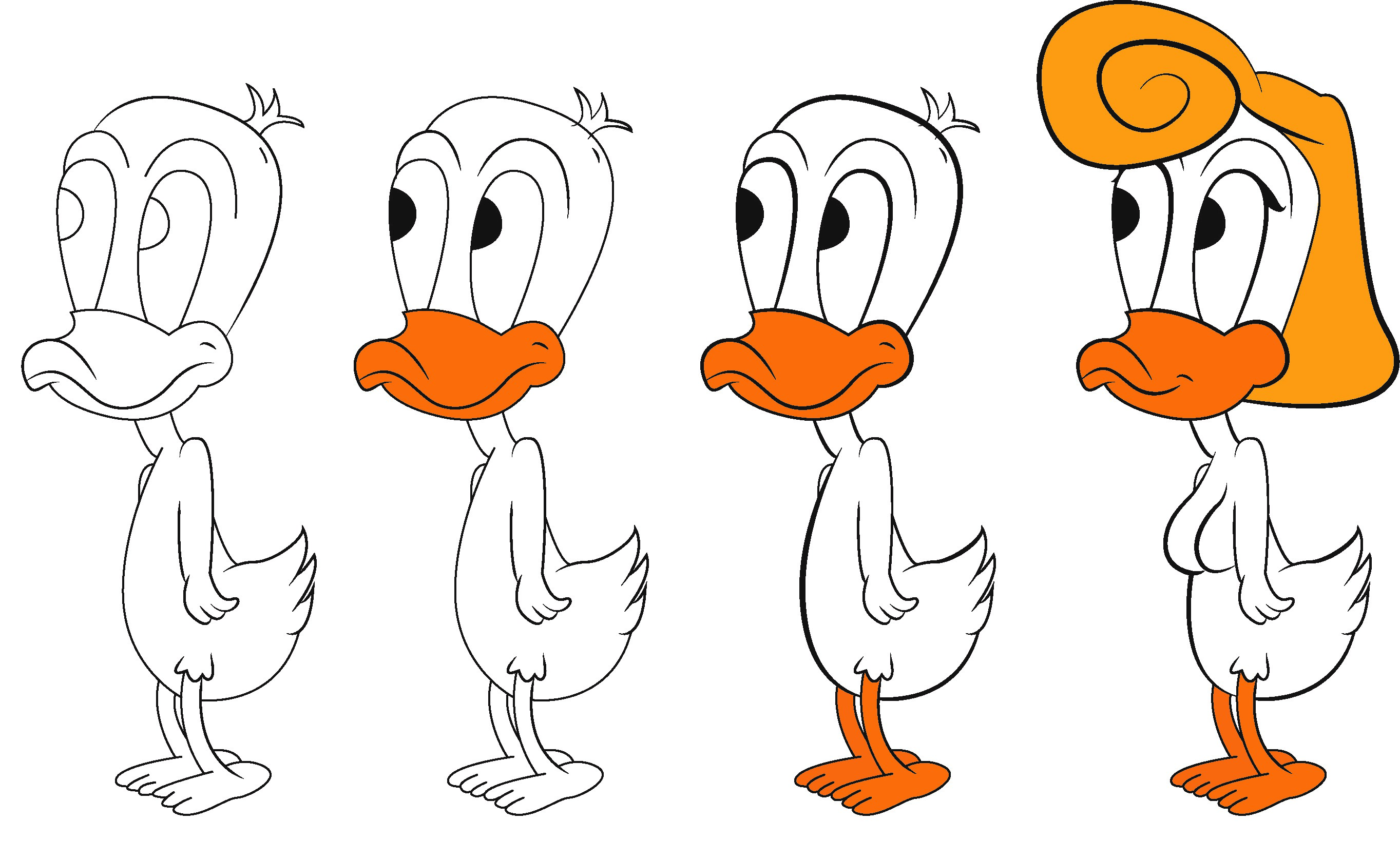
To make the actual designs I began by sketching by hand a rough Hugo design. I then scanned this sketch and within illustrator traced the lines using the pen tool. Once all lines where traced and there where no gaps, I experimented a little with line weights and style. Finally I added colour and converted Hugo to Hetty.
I used the same idea for colourings, keeping the white body and the yellow/orange beak and legs as these are recognisable duck colours that have been used in the media for years. I also utilised the line weights to give the designs a different feel and to try to keep that retro look. To convert Hugo (the male duck) into Hetty (the female duck) I made the eyes bigger, the mouth smaller and added eye lashes, breasts and hair. I decided to keep with a retro esc theme with her hair as well, drawing inspiration from 1940’s woman’s hair styles.
Within my game group I was the lead character designer. I designed the two lead characters and the main boss of the game.
To begin the design process, I started by creating a mood board that contained a selection of images of famous cartoon ducks. The verity contained ducks such as ‘Scrooge McDuck’, ‘Donald Duck’, ‘Count Quackula’ and many more. I decided on the Disney esc design. This was due to the friendliness of the design with the smooth lines and bright yet not extravagant colouring.
For the core design of the ducks I looked a lot at the Donald duck design from the ‘Mickey Mouse’ TV series. It stuck out as it still has the traditional design but seemed a little retro with the line work. The varying line weights and the solid yet memorable colourings add to this.
To make the actual designs I began by sketching by hand a rough Hugo design. I then scanned this sketch and within illustrator traced the lines using the pen tool. Once all lines where traced and there where no gaps, I experimented a little with line weights and style. Finally I added colour and converted Hugo to Hetty.
I used the same idea for colourings, keeping the white body and the yellow/orange beak and legs as these are recognisable duck colours that have been used in the media for years. I also utilised the line weights to give the designs a different feel and to try to keep that retro look. To convert Hugo (the male duck) into Hetty (the female duck) I made the eyes bigger, the mouth smaller and added eye lashes, breasts and hair. I decided to keep with a retro esc theme with her hair as well, drawing inspiration from 1940’s woman’s hair styles.
 Asset and Background Design
<
Asset and Background Design
Asset and Background Design
A key part of any game is the background and the assets. They are what brings the game to life. They need to relate to the story and help It move along bit by bit by adding new assets along the way.
Throughout my team we split up most of the asset design work. The share that I was given was to draw out some ideas for the main part of the level one background and ground blocks for the first level of the game.
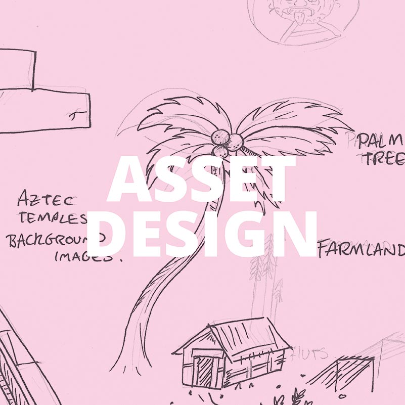
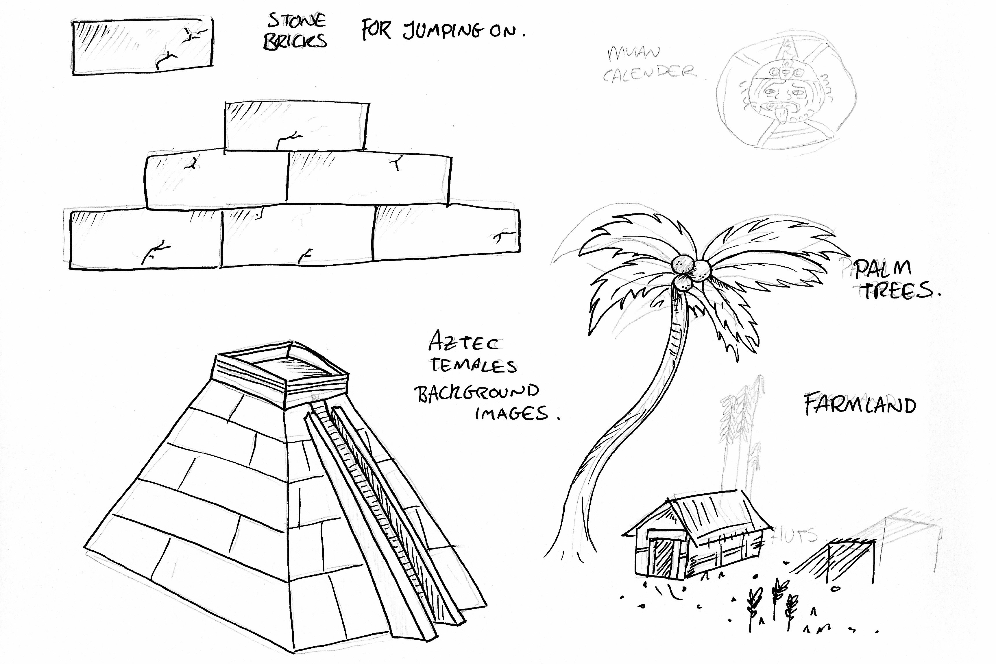
I drew my ideas out using pen and paper. Some of my ideas for the background included Aztec pyramids, palm trees, small villages with farms and the famous Aztec calendar. My block sketches I tried to keep very simplistic but make them look like stone bricks.
Once completed, I then passed my drawings on to another team member who rendered the designs on AutoCAD.
A key part of any game is the background and the assets. They are what brings the game to life. They need to relate to the story and help It move along bit by bit by adding new assets along the way.
Throughout my team we split up most of the asset design work. The share that I was given was to draw out some ideas for the main part of the level one background and ground blocks for the first level of the game.
I drew my ideas out using pen and paper. Some of my ideas for the background included Aztec pyramids, palm trees, small villages with farms and the famous Aztec calendar. My block sketches I tried to keep very simplistic but make them look like stone bricks.
Once completed, I then passed my drawings on to another team member who rendered the designs on AutoCAD.
WEBSITE DESIGN
 Home Page
<
Home Page
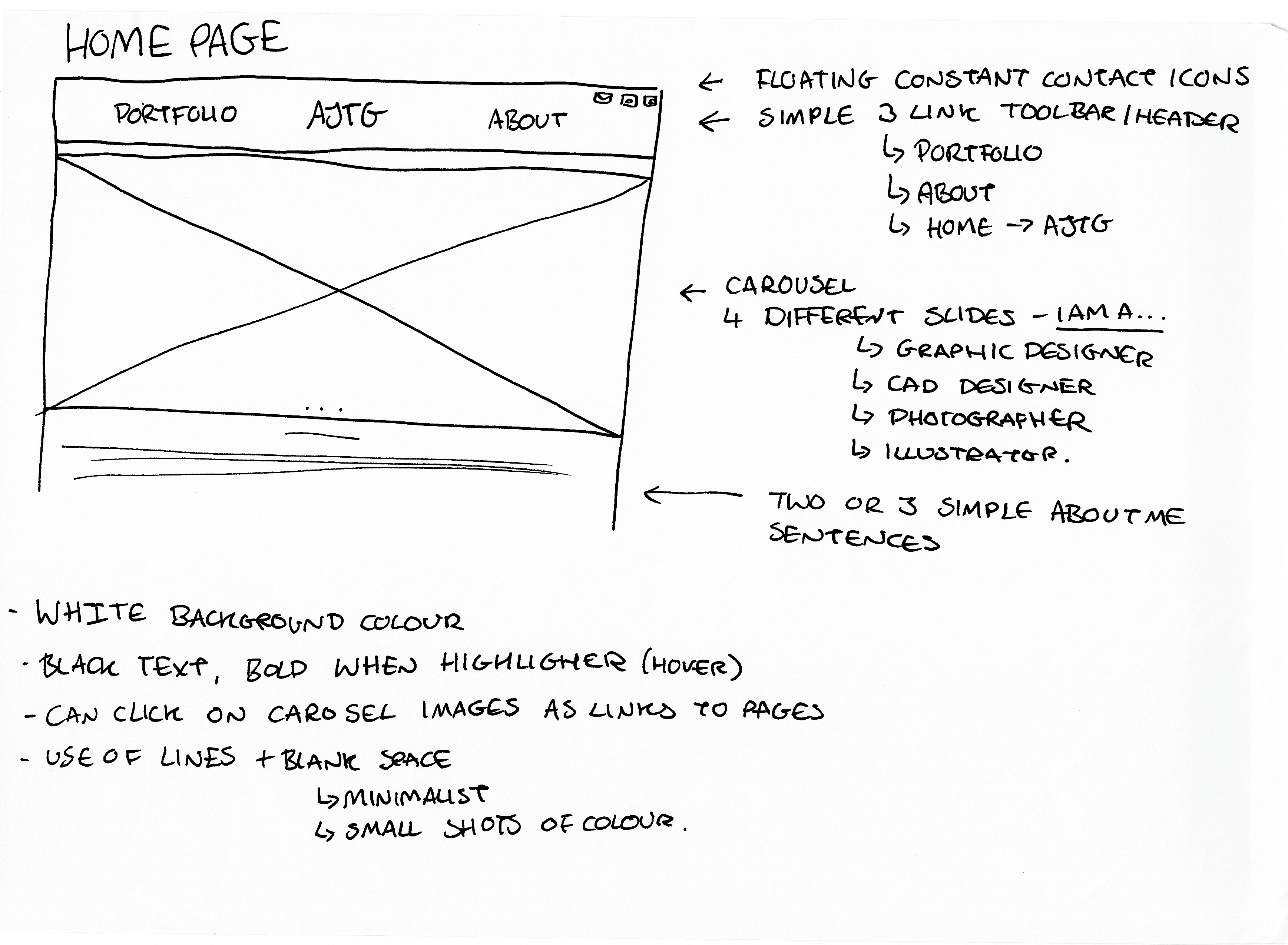
For my home page my ideas varied, but one thing they all had in common was a centred logo in the navigation bar. I believe it looks quite sleek having only three icons at the top. One for portfolio, one for home (logo) and one for the about me page. Just a simple and easy navigation bar that can easily be implemented on every page.
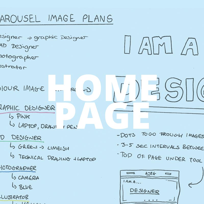
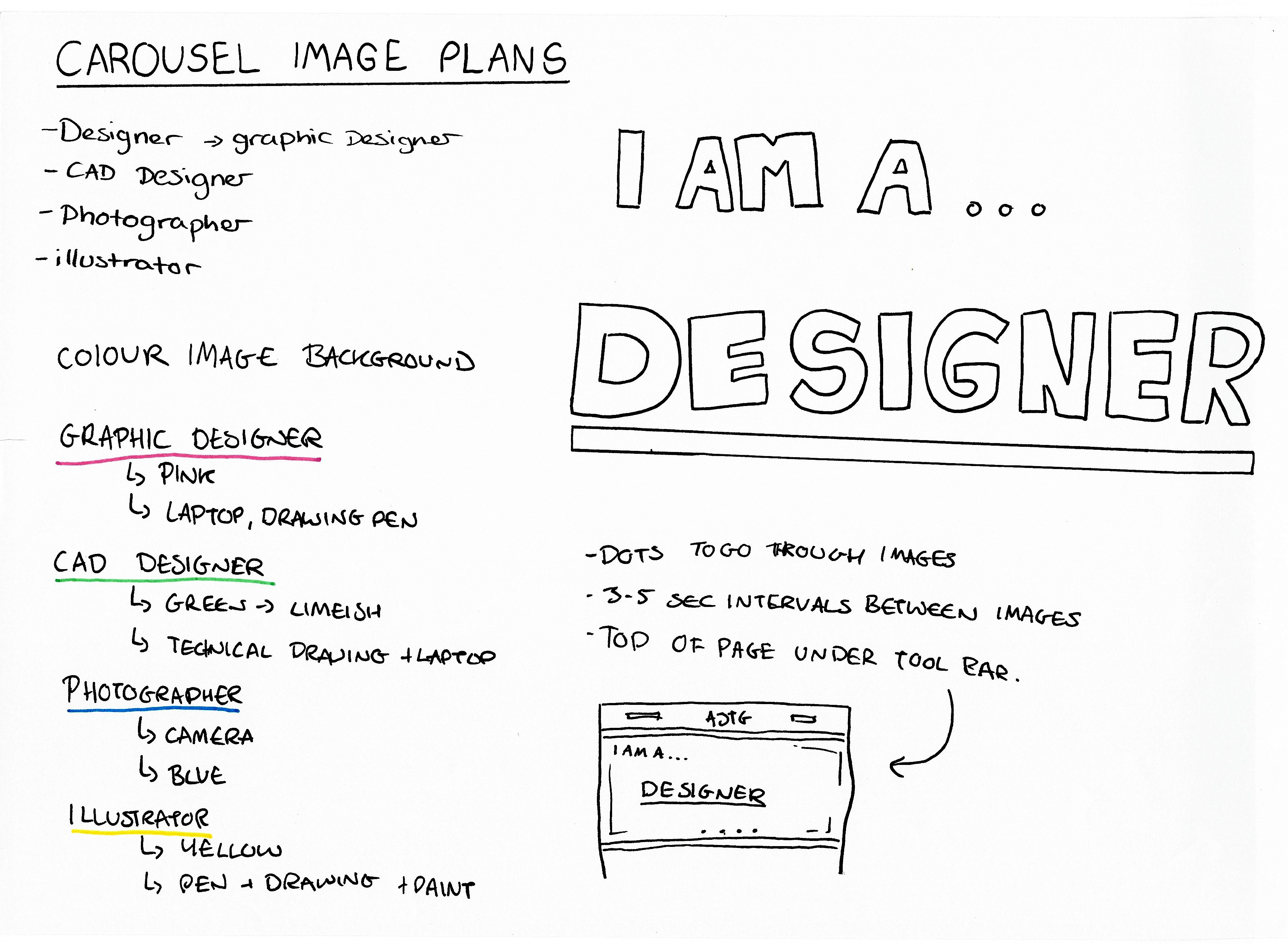
Another thing that I really liked and wanted to include was a carousel. I have seen a lot of effective ones on other websites where they really help to immediately identify who you are. For myself, I do graphic design, CAD, illustration and photography- all of which I wanted to include within the carousel. This is where the colour scheme came from also. I decided on the colours that for me represented each topic. Green for CAD, Blue for photography, Yellow for illustration and pink for graphic design. The images in the background I took myself of items that relate to the topic. For example, the photo for illustrator has some pens and pencils as well as one of my drawings.
On top of the coloured photos there are two lines of text. It is a statement declaring who I am. ‘I am…’ makes it into a point, not a question. This is impactful, which adds to the impact of the photos it is on top of.
With building the page it began of rather hard but gradually improved with the input of bootstrap. Originally, I managed to get the links to work, including the logo becoming a link without the use of bootstrap. But due to my lack of knowledge of html and CSS at that time, I couldn’t figure out how to position the links as I wanted them. When I tried to put the carousel in, none of the images etc even appeared.
At this point I was stuck.

Then bootstrap was introduced
Once I learnt what bootstrap was everything easily came into place. I managed to adapt some code for a navigation bar that I found on w3schools to make it white and include only the three links with the logo in the centre. I also managed to almost seamlessly introduce the carousel with all the images in. At some point I will make the images links, but for now they are just images. I also introduced a footer at the bottom of the page with links to every page. This is carried through on every page for consistency.
I am planning to find a way to make a little tab that will appear on every page just at the top with two icons. One will be for my phone number and the other will direct the user to an email client to email me. For now, this is just an idea.

Another thing that I really liked and wanted to include was a carousel. I have seen a lot of effective ones on other websites where they really help to immediately identify who you are. For myself, I do graphic design, CAD, illustration and photography- all of which I wanted to include within the carousel. This is where the colour scheme came from also. I decided on the colours that for me represented each topic. Green for CAD, Blue for photography, Yellow for illustration and pink for graphic design. The images in the background I took myself of items that relate to the topic. For example, the photo for illustrator has some pens and pencils as well as one of my drawings.
On top of the coloured photos there are two lines of text. It is a statement declaring who I am. ‘I am…’ makes it into a point, not a question. This is impactful, which adds to the impact of the photos it is on top of.
With building the page it began of rather hard but gradually improved with the input of bootstrap. Originally, I managed to get the links to work, including the logo becoming a link without the use of bootstrap. But due to my lack of knowledge of html and CSS at that time, I couldn’t figure out how to position the links as I wanted them. When I tried to put the carousel in, none of the images etc even appeared.
At this point I was stuck.
Then bootstrap was introduced
Once I learnt what bootstrap was everything easily came into place. I managed to adapt some code for a navigation bar that I found on w3schools to make it white and include only the three links with the logo in the centre. I also managed to almost seamlessly introduce the carousel with all the images in. At some point I will make the images links, but for now they are just images. I also introduced a footer at the bottom of the page with links to every page. This is carried through on every page for consistency.
I am planning to find a way to make a little tab that will appear on every page just at the top with two icons. One will be for my phone number and the other will direct the user to an email client to email me. For now, this is just an idea.
 Portfolio
<
Portfolio
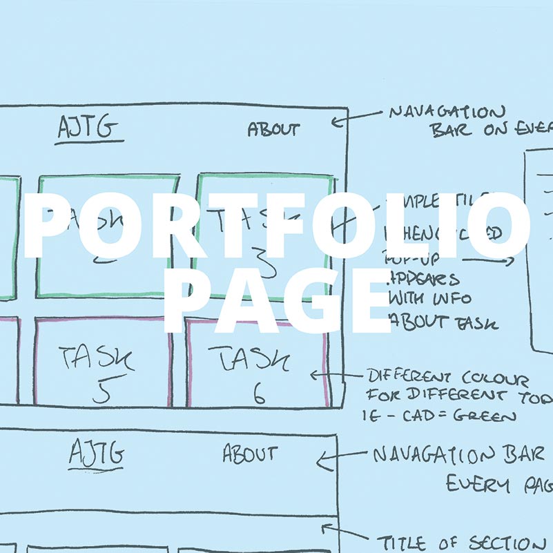
My portfolio idea was really set from the beginning. As with every other page I wanted the consistent navigation bar at the top and the footer at the bottom. I knew I would need a title for each activity and for ease I wanted to separate tasks by lessons. I.e. Website, CAD and game. I decided to use the bootstrap grid and sperate the page into rows of three. As with every design I drew out a brief idea of what I wanted so that I have an image to work from.
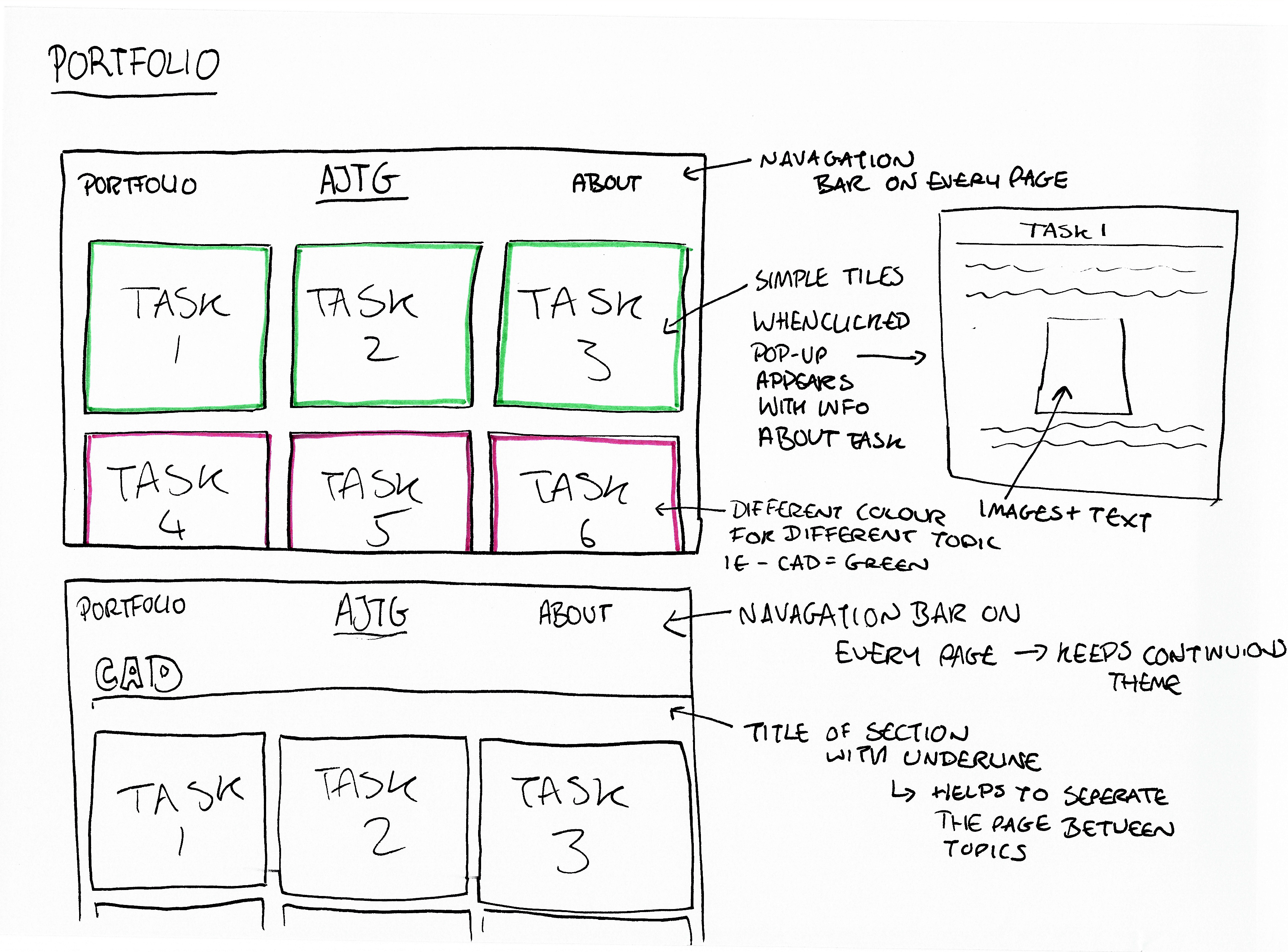
I knew from the beginning that I wanted to use tiles that when clicked produced pop-ups with information about that task. I felt, and still do feel that this is the most concise way of putting my work and information about the work on a page. It means that there isn’t paragraphs and paragraphs of text across the entire page, and that every single task is easy to find and easy to read.
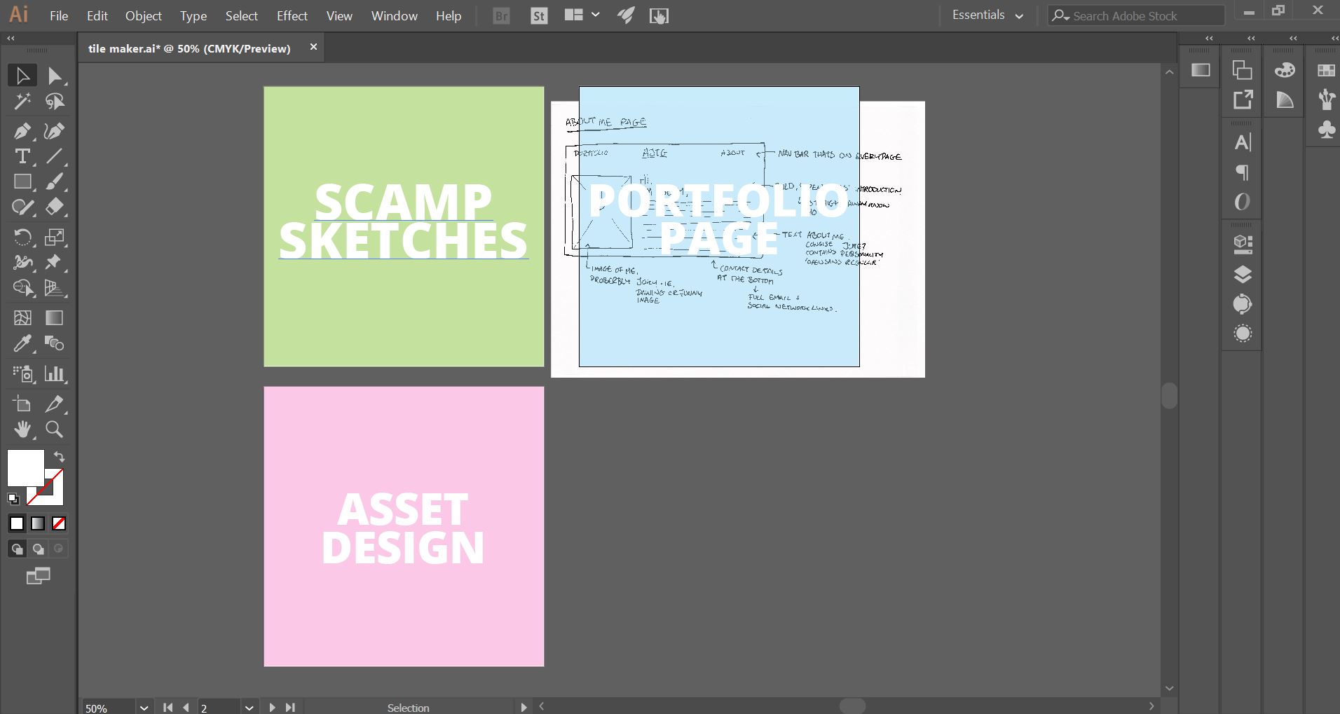
I made all the tiles on illustrator using a template I’ve created. It involved taking the colours from the images on the home page and making them around 50% opacity so that when I put an image below (e.g. A sketch) that image would be tinted the colour. The image in the background would be something to do with that tiles contents for example it could be a sketch from that task. All of the tiles use the font ‘Open Sans’ in Extra Bold, and all are white just for a but more consistency.
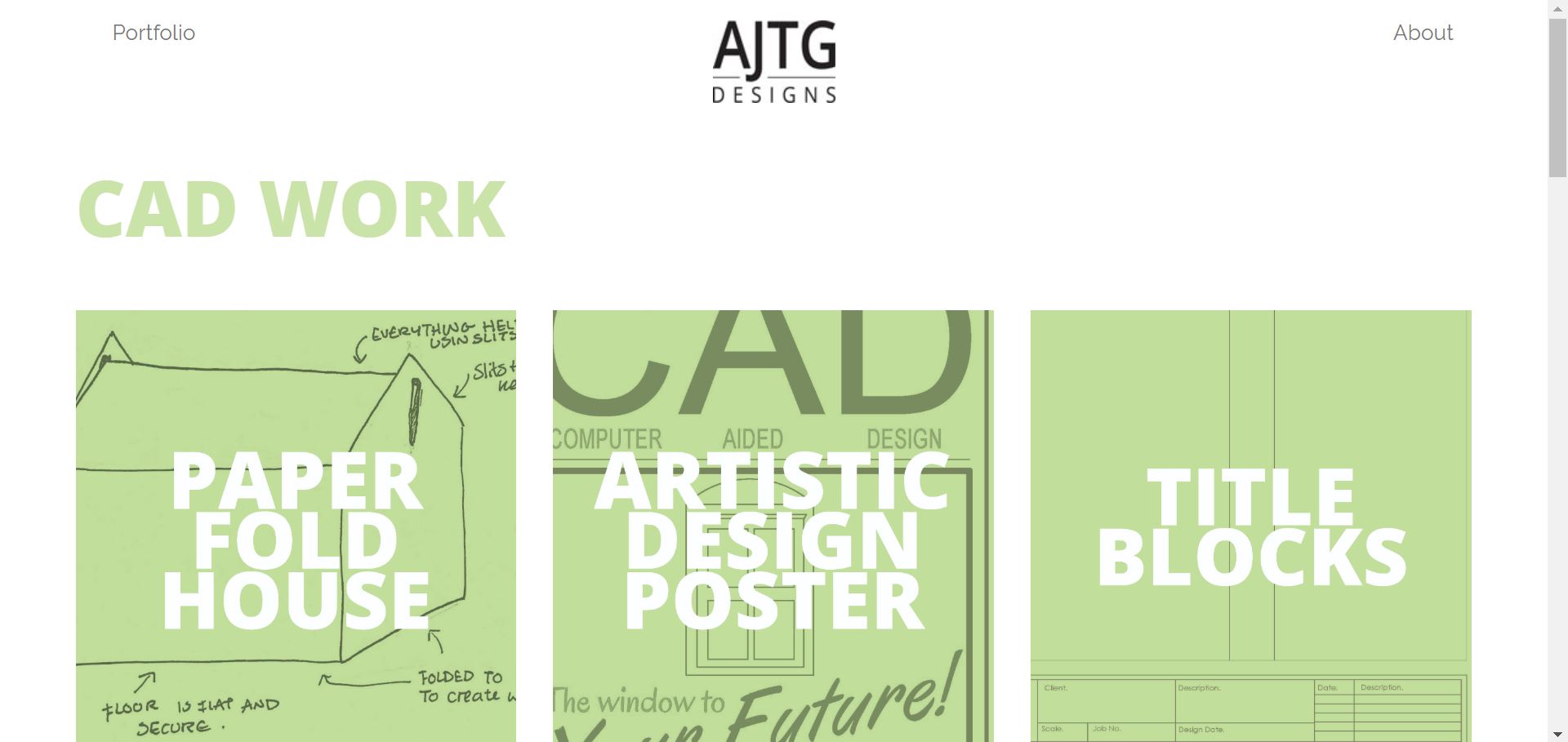
I separated the tiles into three sections; game, CAD and website. Each of these sections corresponds to a colour. Green for CAD, Pink for Game project and Blue for the website. The tiles all have the corresponding colours as well as the title of each section. As I initially wanted, when you click a tile a modal pops-up with information about the task including images of the work all centre aligned.
Across the website for tiles that I either have not yet finished or am not happy with, the tile appears as a black icon with a camera on it. This is an easy and recognisable indicator for that area not being complete.
I knew from the beginning that I wanted to use tiles that when clicked produced pop-ups with information about that task. I felt, and still do feel that this is the most concise way of putting my work and information about the work on a page. It means that there isn’t paragraphs and paragraphs of text across the entire page, and that every single task is easy to find and easy to read.
I made all the tiles on illustrator using a template I’ve created. It involved taking the colours from the images on the home page and making them around 50% opacity so that when I put an image below (e.g. A sketch) that image would be tinted the colour. The image in the background would be something to do with that tiles contents for example it could be a sketch from that task. All of the tiles use the font ‘Open Sans’ in Extra Bold, and all are white just for a but more consistency.
I separated the tiles into three sections; game, CAD and website. Each of these sections corresponds to a colour. Green for CAD, Pink for Game project and Blue for the website. The tiles all have the corresponding colours as well as the title of each section. As I initially wanted, when you click a tile a modal pops-up with information about the task including images of the work all centre aligned.
Across the website for tiles that I either have not yet finished or am not happy with, the tile appears as a black icon with a camera on it. This is an easy and recognisable indicator for that area not being complete.
 About Me Page
<
About Me Page
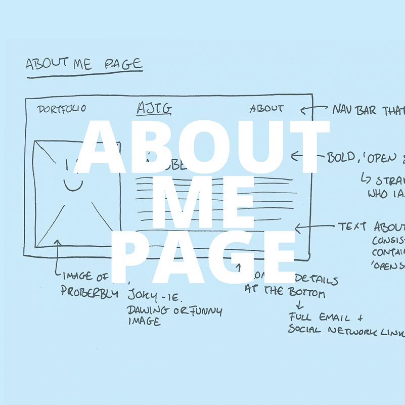
My design for the about me page is simple. I wanted to use two bootstrap grid columns, one the size of 1/3 of the page and the other being 2/3 of the page. The smaller column would have an image and the larger one would have information about myself.
As with any design I sketched out my ideas using pen and paper to visualise what I was thinking. As with every page I included the navigation bar at the top with the three icons. I wanted to keep the main design very simplistic to continue the websites theme. One main colour being in the title, one image and the black or grey text. Nothing fancy, but the simplistic design is easy to read and looks modern, but most importantly it follows the theme.
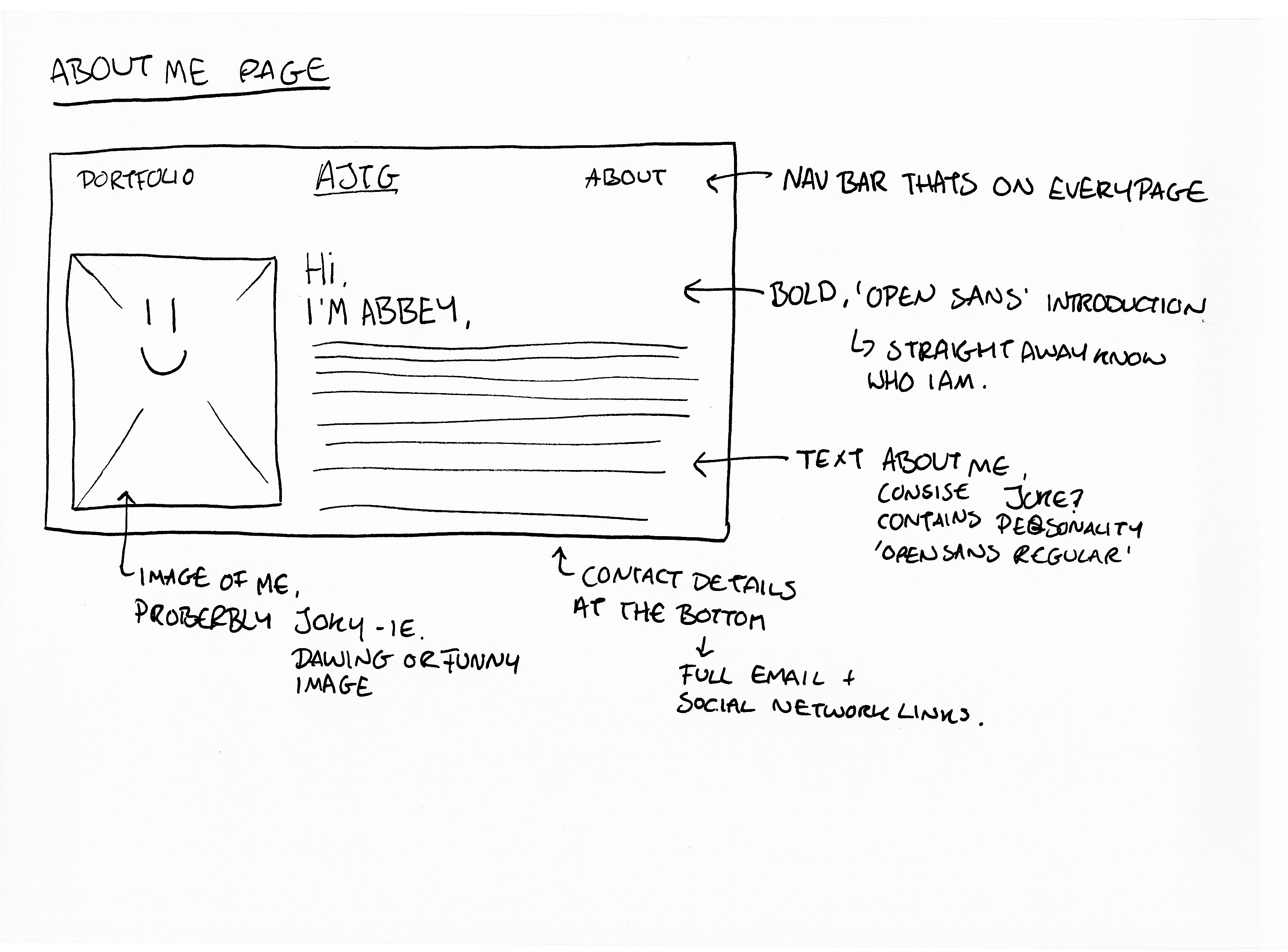
As with every page, the about me page has the continued navigation bar and footer that every page on my website has.
With making the page, I went ahead and used the two columns in the way that I had originally intended. One was a 4 width and the other was an 8 width which made space for the picture and the text. I decided on using the h1 and h2 tags so that the two lines of title text stuck out and was the largest on the page. Both title lines have been made to be the same font but the upper one larger and darker as it declares my name thus is more important.
I decided to put a photo of my rabbit instead of myself for the time being, purely as I am undecided weather to change this to a cartoon version of myself or an actual photo. The main body of text is again in the same font that is continued through the website adding to the theme. It is centre aligned within the column which helps make the page seem friendlier in my own opinion.
Below the text I will put two contact icons, one a phone for phone number and the other a letter for email. The phone once clicked on the computer will pop up with my number, on mobile it will automatically start to call me. The letter once clicked on whether on computer or mobile will open the users designated email program.
For now I have inserted a text block of lorem ipsum as a place holder as I am still updating what I am wanting to write there. Other than that, the rest of the page is complete.

As with any design I sketched out my ideas using pen and paper to visualise what I was thinking. As with every page I included the navigation bar at the top with the three icons. I wanted to keep the main design very simplistic to continue the websites theme. One main colour being in the title, one image and the black or grey text. Nothing fancy, but the simplistic design is easy to read and looks modern, but most importantly it follows the theme.
As with every page, the about me page has the continued navigation bar and footer that every page on my website has.
With making the page, I went ahead and used the two columns in the way that I had originally intended. One was a 4 width and the other was an 8 width which made space for the picture and the text. I decided on using the h1 and h2 tags so that the two lines of title text stuck out and was the largest on the page. Both title lines have been made to be the same font but the upper one larger and darker as it declares my name thus is more important.
I decided to put a photo of my rabbit instead of myself for the time being, purely as I am undecided weather to change this to a cartoon version of myself or an actual photo. The main body of text is again in the same font that is continued through the website adding to the theme. It is centre aligned within the column which helps make the page seem friendlier in my own opinion.
Below the text I will put two contact icons, one a phone for phone number and the other a letter for email. The phone once clicked on the computer will pop up with my number, on mobile it will automatically start to call me. The letter once clicked on whether on computer or mobile will open the users designated email program.
For now I have inserted a text block of lorem ipsum as a place holder as I am still updating what I am wanting to write there. Other than that, the rest of the page is complete.